Haha, nope again, just stating it in general. I don’t recall if I touched on it here or in the other thread, but I mentioned this is probably going to become a bigger issue for others in the weeks or months to come, which unfortunately seems to be the case ![]() and unfortunately, people with not enough experience too it sems
and unfortunately, people with not enough experience too it sems ![]() I’ve got no issues helping anyone who is willing to learn
I’ve got no issues helping anyone who is willing to learn ![]()
I don’t have a Mariko rev out of assembly to test but using another topic as reference this seems fine
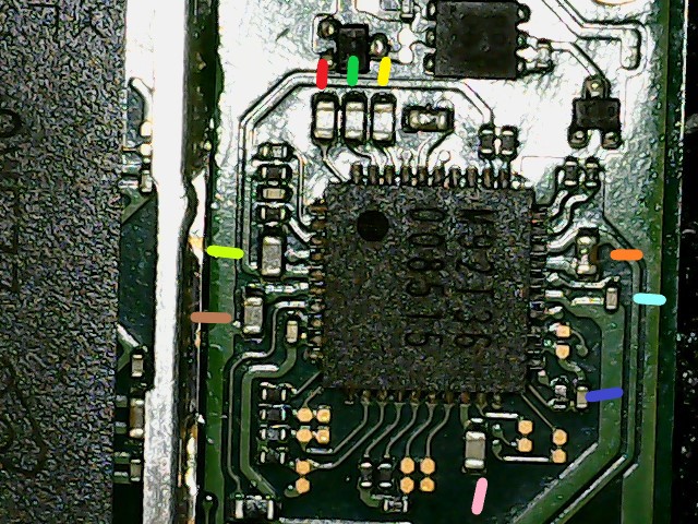
Good, secondary CPU rail fine ![]()
Fine afair, don’t remember what this rail/line is
All one and the same rail in question (boot CPU rail) - all fine for a mariko rev ![]()
One and the same, fine
perfect ![]()
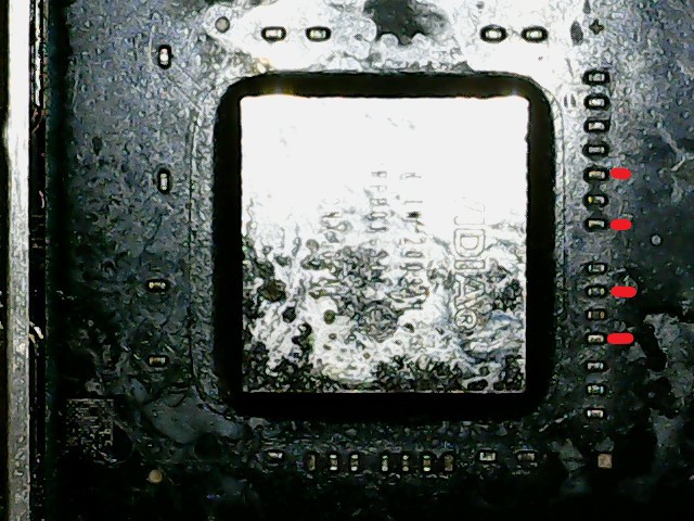
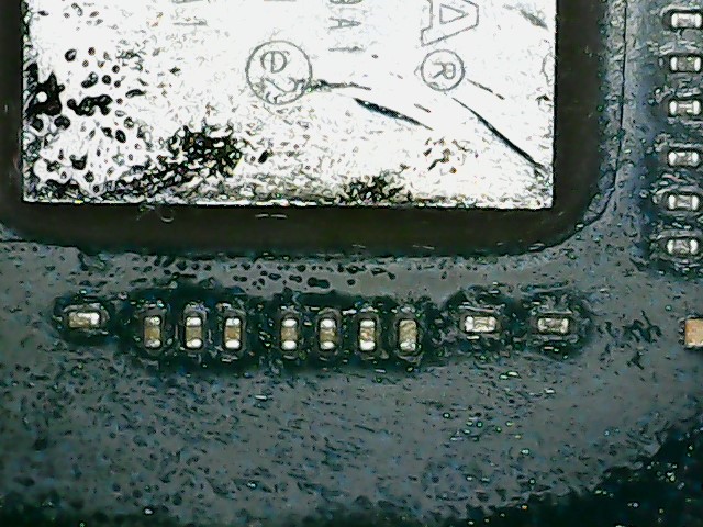
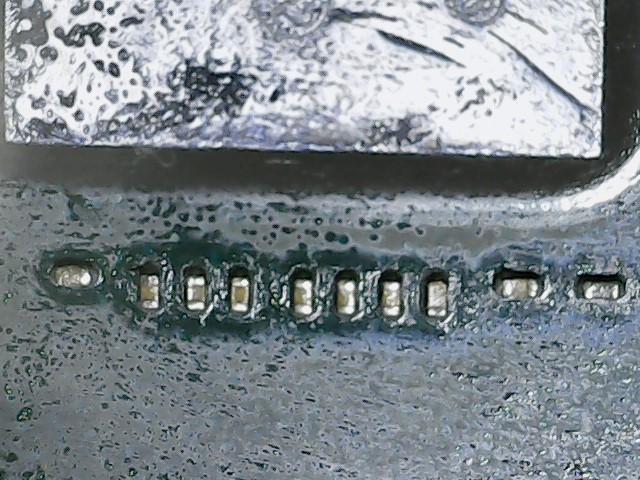
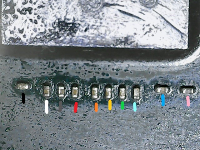
Damn, almost had all of them ![]() Second Ram rail (but of course also has SoC I/O implicated) , this is such a shame and I’m not even sure the cause. Pop your meter in continuity and find the caps (possibly plural, I forget how many) on the SoC which correlates with this rail (red) and take an extremely close look at them for any junk around them or solder spatter, or signs of heat etc (I’m really clutching at straws for you here) I might even be tempted to knock these caps off to take them out of the equation (only if your comfortable and sure you aren’t going to make the problem worse)
Second Ram rail (but of course also has SoC I/O implicated) , this is such a shame and I’m not even sure the cause. Pop your meter in continuity and find the caps (possibly plural, I forget how many) on the SoC which correlates with this rail (red) and take an extremely close look at them for any junk around them or solder spatter, or signs of heat etc (I’m really clutching at straws for you here) I might even be tempted to knock these caps off to take them out of the equation (only if your comfortable and sure you aren’t going to make the problem worse)
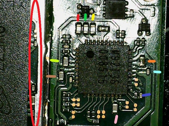
I mean, failing this, I guess you could pull the main PMIC and see if this clears, then after pull Ram… but I expect it’s going to be the SoC in this case. given your other rail measurements it’s highly unlikely that the EMMC would be causing this rail (in red) to be getting pulled down as a by-product as the EMMC’s two rails are measuring perfectly fine (though might also be worth doing just to rule it out, ie. disconnect the EMMC then measure red again)
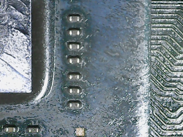
Perfect ![]()
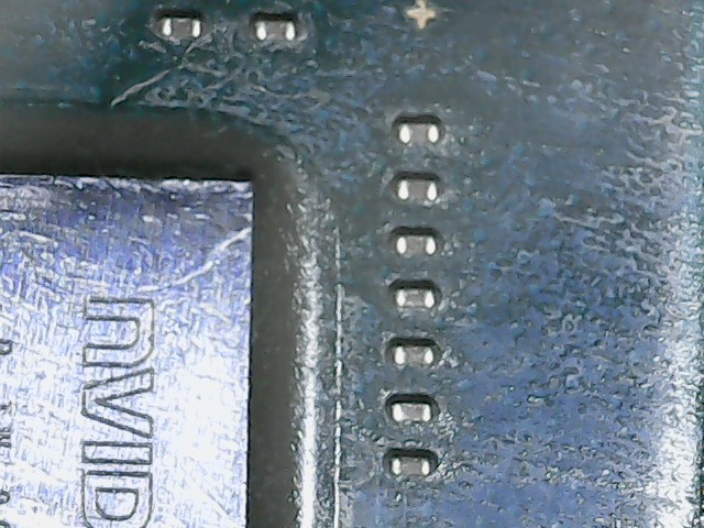
All but one ![]()
I suspect you have two issues, I suspect your EMMC data is corrupt, and I think you have hardware issues. which one caused which fault is hard to say, but you know my feelings on the modchip and the voltage it exposes the switch board to, which again unfortunately tracks with what your measurements I’m afraid