The chip wasn’t from the same seller.
I took it off, it relieved the short. Put it back again, the short was back.
Took another chip from a donor board, and now it’s working perfectly! Soldering an M92 chip is getting easier every time, I’m glad.
I can now hopefully focus on switch #1 as soon as I receive the EMMC reader. Will keep you posted.
I’ve bloody jinxed it. I got a brand new pair of joycons. The left joycon syncs, it’s recognised when inserted (red bar), and it charges on other switches.
Since the left rail is also new, and other left joycons won’t charge on that rail. I think the issue lies on the motherboard. Need to investigate further.
does your fan work? do you have a small diode behind the fan connector on the mobo? That part when it fails will cause issues with joycon charging. There are two small IC’s (usually with a PU marking) that can also affect joycon charging if bad. Obviously usual culprits of contacts, ribbons, and connectors also apply./
In addition to what @coda mentioned it’s also worthwhile popping the pin out on the left rail and checking continuity to/from the contacts to the other end of the ribbon contacts. I’ve got a few of these rails from China (or a Chinese seller listing within EU) listed as “New” but in actuality the rail/s themselves are refurbished with black enamel covering the “defects” in the existing paint with “new” aftermarket ribbons put in (usually of lower quality). I’ve had a few on occasions (much like with the supposedly “new” but in actuality refurbished LCD’s for Switch backlight ribbons) with hairline tears in them or hard folds which breaks the copper traces which sometmes only reveal themselves while wiggling while checking continuity across the lines. Most likely what Coda mentioned is your issue but worth checking
…aaaand the NAND is not recognized. I tried with other NANDs from other boards, it works like a charm with NxNandManager, but that one isn’t. So it’s been a NAND issue from the beginning. Anything I could attempt, in your opinion?
Watch through this series (there are three parts) and decide if it is something you would like to attempt. IMO, if the nand is dead / corrupt, there really isn’t too much to lose to begin with.
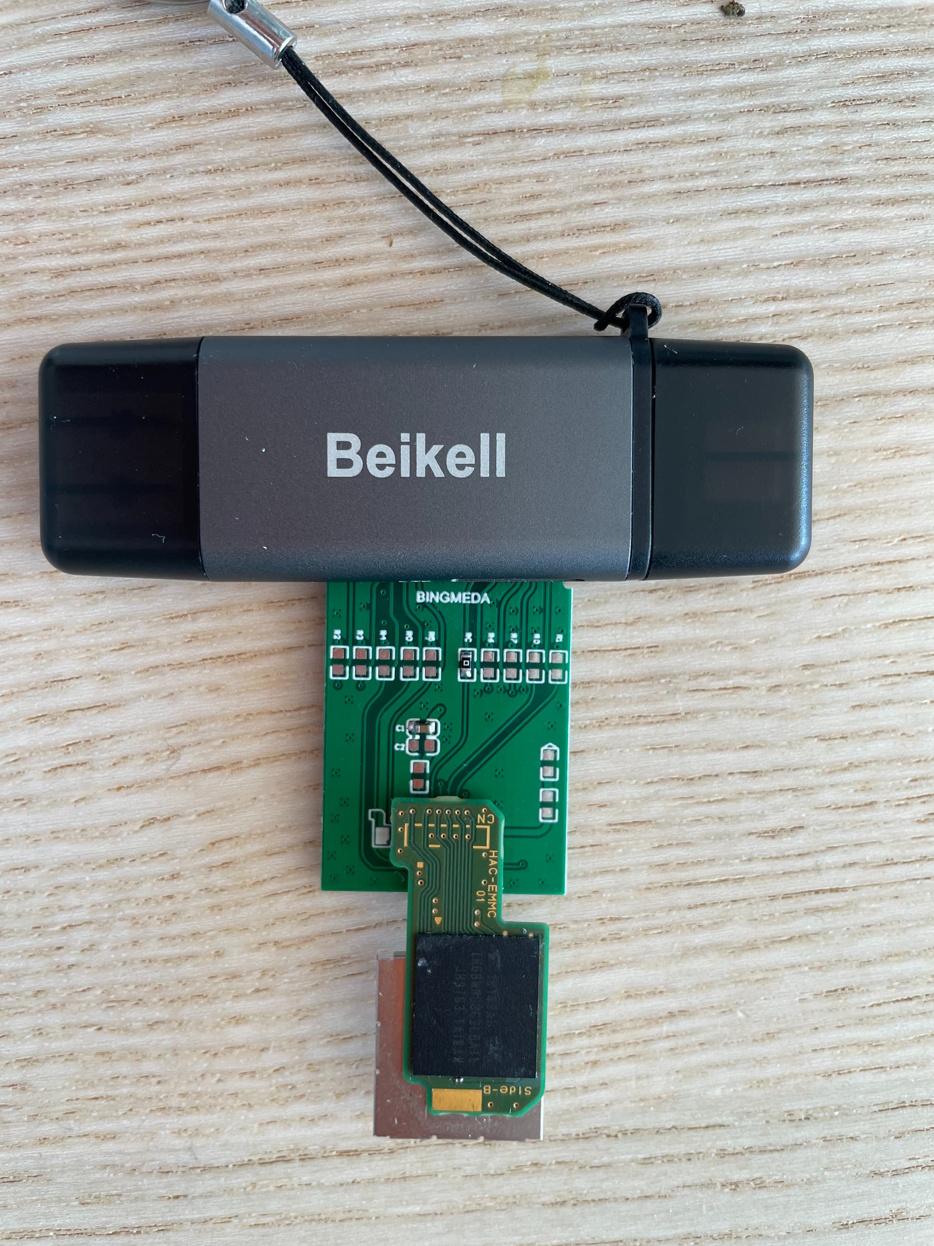
I really do not like the look of this reader you’ve got (unless there is more components on the otherside) as I don’t see any level shifters… perhaps they’re doing it with the reistors (as a resistive divider) but that would still be terrible - avoid hooking anything else up to this reader. (low voltage EMMC adapter is my reccomendation) In theory your USB to SD adapter should be regualting voltage for VCC and level shifting VCCQ but in reality most don’t and some don’t even bother regulating VCC and just output 5V directly
Anyway, as we suspect impact and as this IC is prone to suffering as a result from impact, what I’d suggest for you (at your current level) is hooking up bare minimum hookups deadbug style as opposed to reballing as this IC can be challenging to reball for beginners as a result of the thin PCB. Hookup Dat0, CLK, CMD, VCC, VCCQ up to the low voltage EMMC adapter wire to point, ensure wires are as short as humanly possible and attempt to dump the contents. If contents can successfully be dumped then you can proceed in attempting to reball the IC with stencils and paste and if not you can atleast transfer the now safe data over to a donor EMMC module and get the sytem back up and running.
Failing all that though your not left with many options - atleast not without truly gimping the system or truning it into an android machine - In which case using it as a donor board is best bet
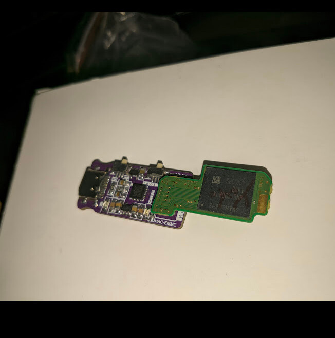
Also - maybe it’s just my eyes but it looks like somebody has soldered something to the EMMC PCB - what’s that all about? is there signs somebody has done rework on this board/IC?
Got one v2 board came in few days ago, stuck at 110mA and no sign of other issue. Wasn’t expected NAND dead, but I plug-in to my reader and it just flashing/loading longer than normal one and didn’t recognize eventually.
Reballed and nothing change, returned since customer don’t wanna pay more for rebuild
Was it a Toshiba IC? these versions are the worst, internal controller dies at even the slightest indication of moisture… I’d not even be surprised if even high humidity can kill them - also had some which seemingly spontaneaously die but it’s usually moisture or impact is the cause. I have been able to recover the important partitions on them while in single bit mode with low heat on the IC and being very quick to grab them. Freeze spray might also serve the same purpose… though the odds of this recovery method working are rare and assumes whatever open/crack/short internally is of small enough area to be relieved due to expansion/contraction with hot/cold
Actually on the picture, it’s another eMMC i used for testing, mine has a QR code on it. The reason why this one is dirty is because I should probably clean my blue mat, which is full of thermal paste and flux
I’m going to go through your videos @coda and probably try your method @Severence as a last resort. If everything fails, maybe try to recall / reflow the IC?
No - as I think we talked about earlier regarding the other IC/s - no reflowing of ICs in a suspected impact situation as there could be sheared/deatached balls floating around below which will only merge where the shouldn’t and likely kill it completely. deadbug is the safest (and easiest) method - your unlikely to find any videos on this subject but I’m sure there are plenty of posts on the subjects elswhere - you can also look at the EMMC pinout for the hookups in the EMMC datasheet (just mirror the pinout image to make your life easier when going to solder the wires
Also it’s worth mentioning this incase you don’t already know. Do not connect any of your other EMMC modules to the board your currently working on (particularly if it’s patched/Mariko) as you risk burning the update fuses - so even if you are able to fix the current issue, if the update fuses are burned the fault symptoms would basicallty remain the same as a result.
Hey @Severence and @coda ! Long time, no news from my end. I feel bad not following up because I can’t stress enough how valuable you guys are to this community.
I had to deal with a lot of things at work and with my family, which kept me away for working on those Switches.
Anyhow, just a quick update: I tried the dead bug method, to no avail. But… remember I got my hands on a donor board from which I stole an M92? As it turns out, it was fixable. Because I did
So now the situation is as follows:
Switch #2 is now fully working BUT it’s not docking. Question: should I blindly change P13?
Switch #1 is now working with the fixed donor board, but there’s something wrong with the battery gauge. It’s always showing as charged, even when it’s obviously not. Should I swap the fuel gauge chip?
PS: I also fixed a Switch Lite, a GameBoy Advance SP (both are very fun to work on) and a pair of joycons (not as enjoyable)
Before you change IC’s, just take a few moments with your meter and test the passives surround the area of the IC’s.
With P13, verify all the filters have vertical continuity (nothing side to side or diagonal). Take a quick look at the traces near the chip and see if anything may have been cut and that all the passives that should be there are there.
Fuel gauge doesn’t have much to it, but check that the 10k resistor is still in good shape and maybe test resistance to ground on surrounding passives and compare to known working. It is a cheap and readily available part that’s also quite easy to remove and put back.
No, check continuity from a usbc breakout board to/from all destinations to check USB/soldering is good and also check your 3V3PDR resistance relative to ground. 1st checks USB, second checks PI3 common rail (which M92 also shares)
Do a visual inspection of the IC on edge like you did earlier for the EN IC, if you see any indicators of damage then yeah. Try another known good battery too just to rule that out.
Hey, it’s been a while!
So just to follow up on everything:
I fixed and gave away both switches… but…
Switch #1 (the one with the dead eMMC) doesn’t really count, since I changed the motherboard with another one I fixed.
I was tidying my stuff after the summer - or to be more accurate: my wife asked me to - and I came across that dead motherboard from switch #1. I kept thinking: such a shame I couldn’t get it to work.
So last Xmas, I purchased a chassis on the French equivalent of eBay, and tried reballing the eMMC chip. The proper way, not a reflow @Severence , I know better now Sadly to no avail.
And that’s when I remembered the video @coda shared, on rebuilding NANDs from scratch. I thought it wasn’t possible for me as I owned a Mariko, not an unpatched v1…
Did some digging, and that’s how I discovered you could mod these boards.
So I got an HWFLY clone for 7 euros, a second hand eMMC (more on that in a minute), installed everything, followed Sthetix video guide, and voilà! it’s now alive!
I’ve learned so much thanks to you guys. I am so grateful that you helped me. And I was researching other things on the forum (how the boot sequence work, etc), and what’s amazing is that you are helping everyone! What a community…
Regarding that second hand eMMC… I got it from a guy who wouldn’t sell it to me individually… so I purchased the whole lot of 3 faulty Switches that I’m now working on.
hola …
solo pasaba a leer unas historia , pero e notado que estas usando mucha temperatura o el aire esta muy alto
podrias mejorar con placas dañadas por completo trata de usar entre 350 a 400 en temp
y de aire depende a que circuito quitar
los ic de contacto trata de llenar con estaño nuevo y tambien el puerto rellena primero conestaño nuevo y luego aplica calor y todo al 100!>>
excelencia para todos