Not seeing anything with a hex code. Looked through the program files as well in case there was a log but not seeing anything.

Unless it’s that 0x0000 message.
Edit: Oh yeah, that is it. Patched. FML.
Not seeing anything with a hex code. Looked through the program files as well in case there was a log but not seeing anything.
Unless it’s that 0x0000 message.
Edit: Oh yeah, that is it. Patched. FML.
Haha yeah patch confirmed ![]()
Not to worry, just go through what we talked about, I assumed it was patched from the beginning ![]()
You wouldn’t happen to have a link for that boardview for the switch lite, would you? I’m having trouble finding it.
Some voltage readings around the ENXX IC. These seem right to me. I’d trace them further but they just seem to vanish into the board. ![]()
Maybe I should try replacing the M92? I know it can be an issue even if shorts don’t present themselves.
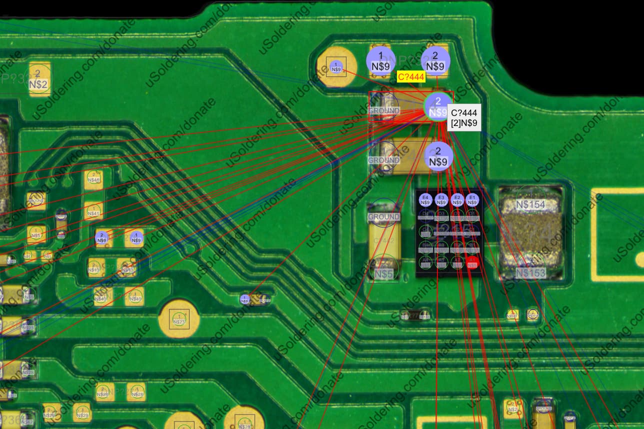
I think I found what you meant about boardview and the switch lite. But this may as well be written in Greek. “C?444 [2]N$9?” What is that even supposed to mean?
I feel close. I found this part on the switch lite that goes to that same 3.3v point near the max chip.

Didn’t find the exact thing, but something very similar on the switch.
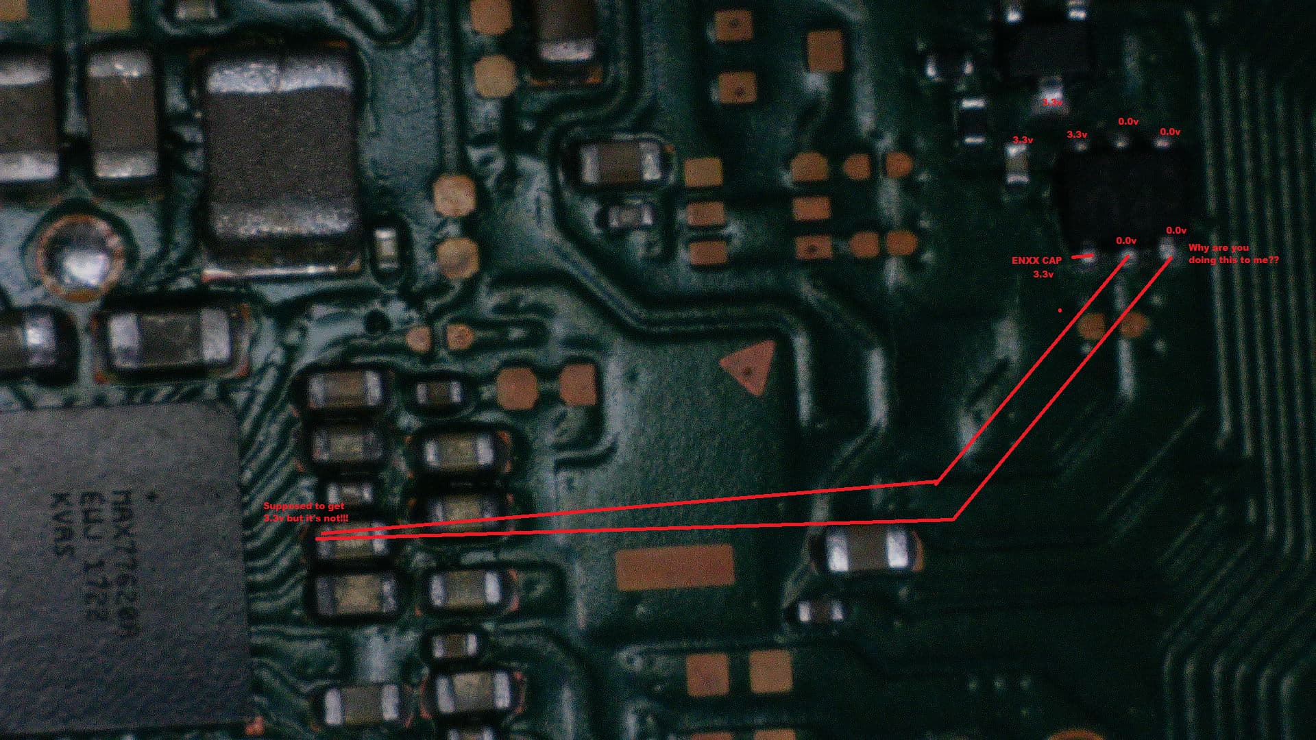
So I took voltages around the PU chip, I can see where it’s coming off that transistor, the resistor, the cap and then going into the top left leg on the IC, I get 3.3 off all those points, but I don’t get it anywhere else on the PU IC, specifically those legs that connect to the 3.3v point near the max chip. I thought I can finally solved it. Surely there’s something broken inside this IC that’s making it so the voltage doesn’t come back out again. So I swapped it with another one and…same thing…Voltage going in, nothing coming out. ![]()
Yet again, I’m lost.
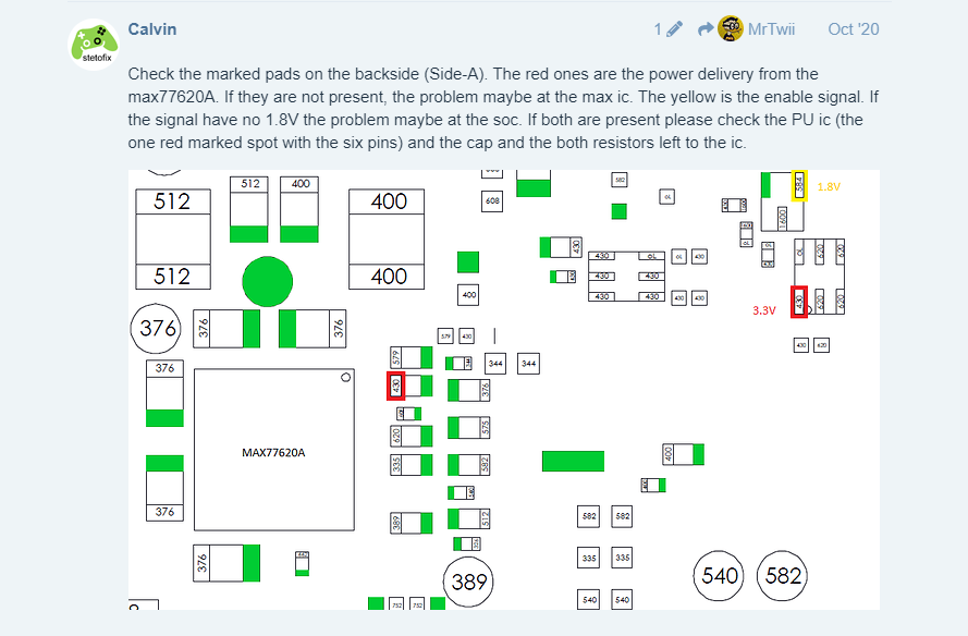
According to Calvin’s post, I should be getting 1.8v on the upper right pin of that transistor before the PU IC. I’m not getting 1.8v, and according to him, that’s an issue with the SOC. So it’s possible I’m screwed here, assuming that’s correct.
Wondering if I should supply my own 1.8v to that leg and see what happens…
no wait up bud, lot of stuff you’ve done recently which i’d have to confirm prior, and/or wait for confirmations from someone else, I’ll take a look tomow, it’s a bit late here now. Don’t rush, the same beginner mistake i mentioned earlier is related, acting too quick and causing inadvertent issues ![]()
Oh don’t worry, the second I posted that, I could hear your voice “Don’t do it! Don’t do it!” I resisted the urge. lol
haha ![]()
Ok, so I looked over the boardview and a board in person and buzzed it out, near the PMIC the cap you’ve highlighted, so to confirm (and as you know) this isn’t the rail provided by the ENXX IC but it will be when what i assume is a fet (which is in @Calvin image) is turned on, I’m guessing the 1.8V is gate voltage and comes by way of the transitor and it’s getting that by way of the SoC, again all guesses as i didn’t go too far back with buzzing things out / looking at the boardview.
But, given the charge current which = braindead state this could all just mean your not at that stage in the boot process yet, so none of this really tells us all that much i’m afraid. I’ll have a think maybe something will spring up in my brain ![]()
Whats the current draw on a 5V supply out of interest?
5v, .48a. I tried to connect a wire to the leg where that 1.8v should be coming in, and I probed the entire board for over an hour just to see if I could find it’s connection point, but like Calvin said and like boardview seems to indicate, likely coming from the SOC.
So, I guess my only option at this point is to throw in the towel and have yet another parts board or try to reflow the SOC in case it’s a broken solderball joint. Bummer.
indeed.
Trouble is, we don’t know if your at that stage in the boot process or not and the problem likely lies elsewhere, so this may be a non issue and you have found yourself down a rabbit hole. One of the reasons I don’t check these points, specifically the point at the cap which the retrosix wiki has lead you to is because in order to actually provide any useful information to the repairer we would have to know a variety of things, such as, what is the purpose of switching 3V3PDR to this line going to the PMIC, for instance is this a “rail power good” inout for example or, or, or, then further back what has to happen prior to the SoC allowing this to happen, does the 8316 IC rail outputs have to be high in order for this condition to be met (for examlpe), or maybe the backlight IC, or maybe the fuel gauge has to report in over I2C before this happens, and the list could go on and on and there could be a variety of other factors,on top of that which can and does alter rail order amongst other things such as board revision. This is why I say it’s kind of pointless trying to lump yourself into a particular stage of boot unless you know about every single rail or condition on the board etc etc which is simply not possible. For now, I’d ignore this unless you can get a datasheet for the PMIC wich last i chcked you couldn’t) or you know all other conditions mentioned (which is never gonna hapen I’m afraid)
I hope that all made sense, basically your in a braindead state which could be for a variety of reasons and I’d imagnie that 3.3V not being present at the point on the PMIC is probably semi-common on boards in this state a bit like in the same way 1V35 is typically not prsent on Mariko rev boards when they are in a similar braindead state.
Unfrotunately being ni a braindead state can be caused by a variety of factos such as bad EMMC, bad fuel gauge, not present primary rails (emphasis on “primary” here) , sometimes 8316 issues, ram issues, SoC issues and the list goes oo and on I’m afraid and unfortunately because there is so many potential causes I can’t point you in any single direction. Best I can say is check the forum for people in a similar boat and start narrowing things down, don’t go near the SoC or Ram til last. Also while i don’t particularly like them a modchip might be helpful here for diagnosis. When I mentioned earlier pretty well all the boards i work on these days are in same/similar states to yours. they can often be fixed but it just takes a lot of time and banging your head against a wall and you might even find yourself reballing the SoC or other towards the end ![]()
Was there anything else which may be relevant that i don’t know? wre there signs of lquid anywhere, signs of prior rework, signs of board warp or anything else of that nature?
Also, I’ll just say this before I forget, following your change of the PMIC, your weren’t getting any form of USB detection right? then after you were right?
So if the answer to the above is yes (and assuming no other issues, for example probe slip and inadvertant short in this timeframe window just as an example) then we can reasonably assume one of three possible things. 1: the PMIC install was bad or the IC used was bad 2: this is completely unrelated and something else has coincidentally failed or deteriorated (for example the EMMC, thus putting it into an RCM state) or 3: the the heat used during your rework of the PMIC has resolved / relieved a joint related issue or IC issue, likely temporarily
Case 1 and 3 would be the most likely and then you’d probably hone in on any potential SoC / Ram issues, though as mentioned previously this is all a big hypothetical and you’d want to leave messing with SoC and ram last on your list. You can however try putting mild pressure on the SoC or ram while prompting the console to boot and see if there is a change in behaviour, sometimes this works, sometimes not, depends if there is even joint related issues with the SoC / Ram and if there is the severity.
And to add to the previous post regarding all the potential causes of a braindead state, just to say sorry, wish i could go through everything one by one and how to diagnose and resolve any potential issue but my post would be longer than that entire terrible retrosix wiki guide, but there is posts by me and others on each individual potential culprit and diagnosis etc with a bit of searching which i know is a bit of a pain. For example we’ve basically ruled out your ENXX IC as a potential issue already here in this topic, so you just wanna start ticking things off the list ![]()
It seems to indicate that it’s only hitting the first boot stage and not the second since it stays at 200ma on my bench power supply and never makes that second jump to the 400ma, although that info comes from that wiki, so I dunno.
Nothing else that would be relevant as far as I know. Nothing looked amiss, I’m quite certain I was the only person inside of it. The only strange thing are the caps around the one max chip are shorted, but by shorted I mean 50ohms resistance, so I get a beep, but it’s not a dead short so I dunno. I don’t seem to get it on working boards but everything I can find seems to indicate that around 50ohms is correct.
I wasn’t getting detection at first, but I think it came and went. Even after I changed the PMIC, it would sometimes connect and register as that APX or something and then the Tegra software could see it, so I would venture to guess that changing that PMIC didn’t really change anything, I was just getting connections irregularly. You’d think that would mean the port might be bad but it looks ok.
I can apply some pressure to the SOC and RAM as it’s a simple thing with no real harm. I don’t recall slipping any probes. I’m pretty careful and I rarely even probe while the thing is powered, and when I do, I treat it like I’m defusing a bomb. Doesn’t mean it can’t happen, but the entire board seems to act exactly as it did the first time I took it out and started poking at it, even after replacing a handful of components.
Squishing the SOC and ram did not yield any results. The only other thing that might be worth mentioning is that this is what the previous owner had used to charge the system. Clearly not something nintendo made…
I see, provided USB port is all good (and your cables) and you’ve verified it with a USBC breakout board (ie. Checking resistance to/from destinations and ensure a low and consistent ohm reading, even while wiggling, at least if you wanna make doubly sure) this would further point the finger towards the SoC / Ram as this is pretty common in that scenario, chance it could be still be something else throwing it in and out of an RCM state elsewhere too though, for example intermittent EMMC etc.
What’s it’s output voltage, just a standard 5V USB adapter?
One of those variable ones. Can do 5v or 9v.
I don’t imagine the output would even jump to 9V when used in a Switch, unless this one is? though you do here horror stories with these… lot of the USB lines go straight off to the SoC