I seem to have this bad habit of buying Switches that don’t have the usual M91/BQ/PI3 issue, but some other various issues. Usually those boards become parts boards, but I’m full up on those at this point and would love to get this one solved, but I’ve reached a bit of a dead end.
I’ve checked the resistance and voltage drops with my multimeter and most everything seems to be fine or at least, close enough (although, that’s just my wild guess. Not sure how much variation I should be worried about…).
What I found:
The issue is that it’s clearly not reaching it’s second stage boot. It draws 200ma on my bench power supply but never jumps to 400ma, indicating it’s never getting to second stage boot.
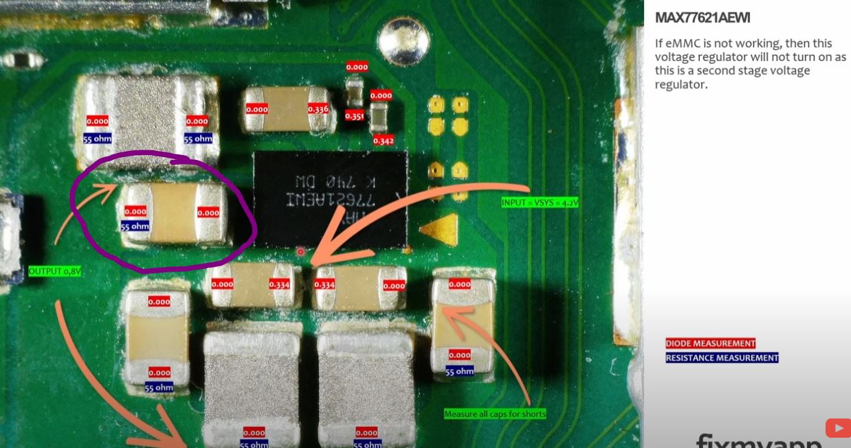
The only “short” I seem to have is circled in purple in the first photo here, however it’s not a dead short and is it reading about 50ohms resistance, which according to the photo, is accurate? So maybe it’s not a short? It’s strange.
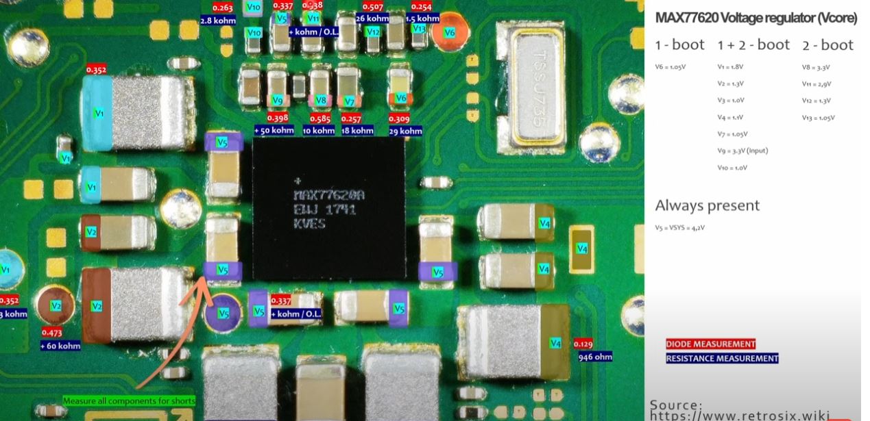
I checked voltages around the MAX7762 IC on the back, with the battery plugged in and the usb-C cable plugged in, and I have voltages on V1 through V7, however I find I’m not getting 3.3v on V8, which is why it’s not going into the second stage boot?
So I guess the question is, what supplies the 3.3v to the V8 cap on the back of the board? Could that be the thing causing the issue?
Before anyone asks, it’s not an emmc issue. I have an RCM loader and that did not detect an RCM when plugged in. I tried both a loader to inject the package and via my PC and neither worked. I really think it’s that missing voltage issue, but I’d love to get your thoughts. We can’t let this one beat me!
I always get worried when i see people following that retrosix wiki… riddled with errors, bad info, dangerous advice and flat ut just made up info… at least it was last i looked, and to call it a wiki… but you can’t actually correct any of the bad info… so not actually a wiki at all.
Anyway, I guess the 3.3V rail your mentioning, not that I’d usually check for it at the PMIC, but i’d guess it’s the same 3.3V rail provided by the ENXX IC, nearby the realtek audio IC.
This does not conclusively confirm you don’t hve EMMC issues. you can have a bad EMMC and still be in a non RCM state and vice versa
Anyway, you might wanna search the forums, I made a post here a while back identifying the ENXX IC as well as the pinout, when you’ve found it you’ll wanna confirm the ENXX IC is even being told to turn on ie. is the enable line high.
Good to know. It’s not the only thing I use, but I sometimes have to go off what I can find out there, it’s hard to verify anything.
I had checked there and was getting 3.3v.
I would suspect that if I wasn’t also not getting all the other second stage boot voltages as well. Something is keeping all the second stage boot voltages from showing up. Maybe it 's an EMMC issue, but if I can’t get it to not be in an RCM state, I’m not sure how to resolve that.
I did decide to replace the MAX77620A, but same results.No Second stage boot voltages. This is a strange one.
hmm maybe it’s a different rail then I’ll have to check on this but I know 3V3PDR (which is the rail provided by the ENXX IC) does make it’s way to the PMIC though i haven’t double checked to see if the one you highlighted is the same, I’ll look into this later.
trouble is your using the terminology from that daft “wiki”… while i understand what he’s trying to say by “second stage” etc etc his info is just so bad from the get go that you wanna avoid using it, basically different rails come up at different points following a prompt to boot, while it would be nice to say your in a X or Y stage the reality is it’s a one after another kind of deal, and unfortunately I’ve never taken the time to map the rail order out (nor has the person on that “wiki”) so it doesn’t really say much, so as a result you can chase rabbits down holes.
Not really sure why you did this, there didn’t seem to be any indicators that it was at fault, trouble is you kind of muddy the waters when you change things without cause
an RCM state can be for a variety of reasons, simply disconnecting the EMMC module will put it in an RCM state, using the jig and a few other causes. Being stuck in an RCM state on the otherhand can be the reverse and more, such as SoC problems and more.
Honestly, I’m just grasping at straws. I wasn’t sure where else to go. Luckily, it shouldn’t muddy the waters too badly, as it changed absolutely nothing. I won’t claim to be a master reballer, but it seemed to go just fine.
At any rate, I’m at the verge of giving up anyway since I don’t see any further paths forward.
I’ll take a look on a board tomow and see what 3.3V rail that [terrible] source was referenceing and see if it’s actually different from the one provided by the ENXX IC etc and let you know, @jkyoho@Calvin might know off the tops of their heads as they’re knowlegable on these things but if not i’ll check tomow
Also I wouldn’t give up, you’ve basically tried absolutely nothing and your all out of ideas gotta say, every board i work on is like this, i never have simple cases anymore… can’t tell you the last time i only had to replace the M92 IC or otherwise on a switch… everythings complex, but it’s the best way to learn
Oh and while I think f it, think there is a boardview for lite which you can find on the forum, the PMIC is pretty well the same on lites so you can check yourself what/where that 3.3V is / coming from
Very true. Seems like everyone else gets some visual clue or at least find a short somewhere. I have none of those things. Diode and resistance all seems within expected values, but maybe I should do some more probing.
This is for a regular switch, not a lite.
I should also mention that I’ve replaced the PI3 chip as well since I found online that it could result in 15v, .4a draw. Didn’t change anything of course.
Seems like your board is basically in a braindead state which i’d estimate probably 99% of all recent boards i work on are, unfortunately there is no one size fits all solution to this problem and have to be dealt with on a case by case basis… this is why that terrible guide ain’t working for you because this is not a binary scenario which that guide tries to present in all cases which these situations never are.
Right i get that, but lite and regular are mostly the same, and the PMIC are near identical, so you’ll be able to see in the boardview where that 3.3V rails is coming from, I mean i could do this for you but you won’t learn anything
again, your doing the classic beginner mistake of messing with things that are unrelated, i understand someone made a post etc on the topic but you have to prove somethings at fault prior to doing P13 is for dock functionality, nothing more, while a fault on this IC could pull the voltage low, you’d very easily be able to prove that with your meter in seconds prior to ever considering removel etc
Got it. I’ll take a look and see if I can figure it out. Do you think all those other second boot voltages also come from the PMIC since they’re less than 3.3v?
Oh man, for funsies I decided to just plug the board back into my PC and this time it came up as APX and it asked if I wanted to install the driver, which I wasn’t getting last time, so I did and now it’s detecting the RCM. So something changed here. Could be an EMMC issue after all. Will report back soon.
ah, ok, then just assume for the time being that it’s patched and work through the info i’ve gave you thus far, if it was patched then it’s behaving how you’d expect
They will all show as successful, it should spit out a code in hex following injection which further clarifies if patched or not, can’t remember off the top of my head which is which tbh but you might wanna post the code is spits out, 0x some other decmals trailing