BGA flow tips + "ghost" input

Good day,

I got a switch here that was able to turn on and be responsive, but the button input wasn’t working well. My cross directional buttons and the minus button didn’t respond, or the bumper L button.

I opened up the board and there was a lot of corrosion and indication for water damage. The daughter board was soaked, so I replaced it with another daughter board from a doner board. That went well. All buttons were responsive, except for one thing.

For some reason, when I pressed on any button, it would exit the button input test because it suspected that the button was being “held” down.

I looked around the forum for any related problems and there was one discussed about “ghost” input. Their solution was to reflow the CPU and the “ghost” input was gone.

I decided to do that first before deciding to switch the button input IC from the donor board.

Well now the switch doesn’t turn on…

Also, when trying to reflow the CPU, it.wouldn’t.budge…

I have my hot air gun for 460C at 55% air flow. I applied flux before the air flow and during the air flow, but it still wouldn’t budge when I try to push it slightly with tweezers.

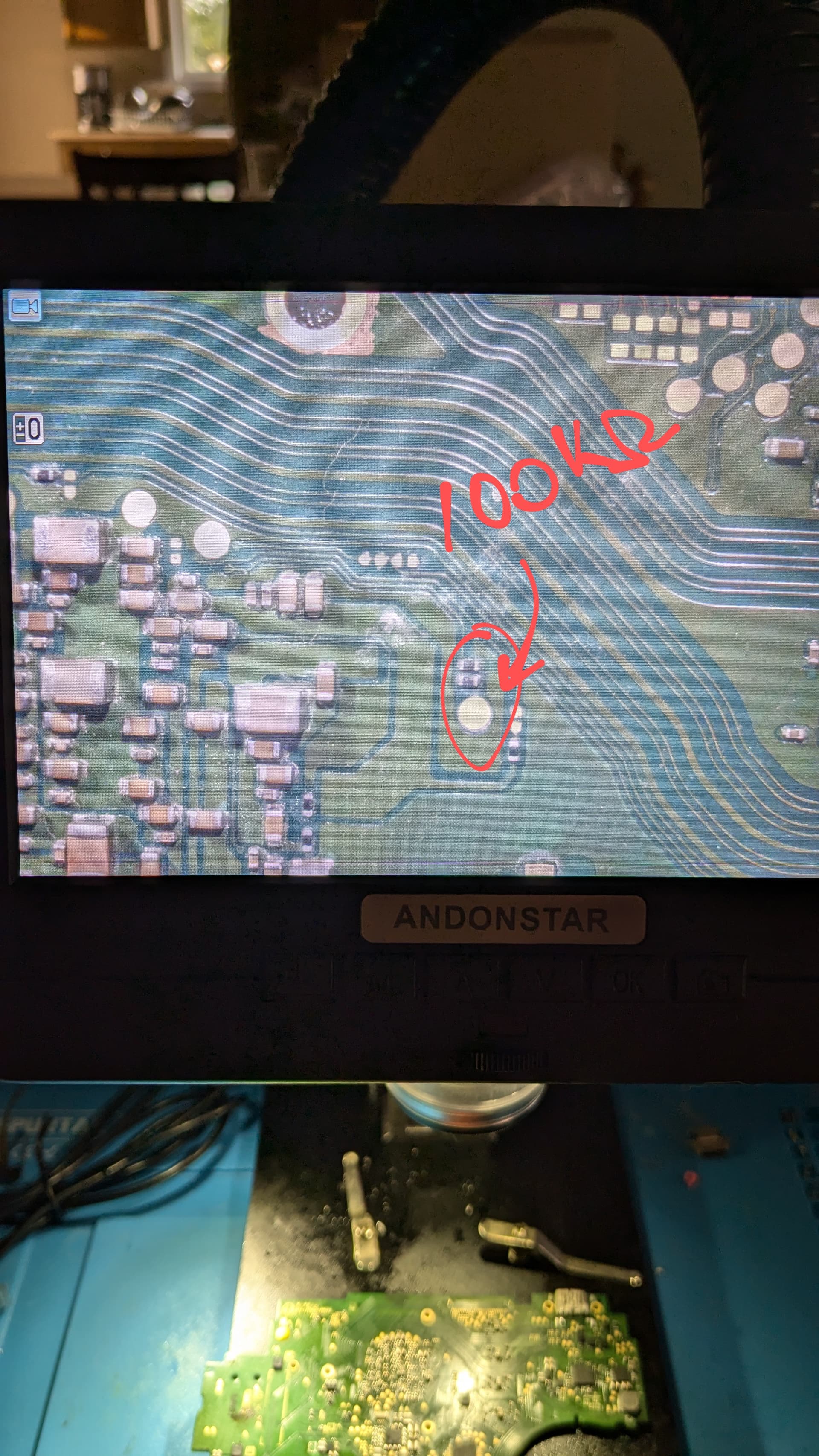
Now on the back of the board with the field of capacitors, one of the test points reads 100kohms, which on a good working board would be roughly 28kohms. So I know I did something or I bridged something somewhere.

But my main concern is the that the bga isn’t budging. Do any of you have any tips to slightly budge bga’s to reflow the solder? It’s like I’m applying heat on a stone.

Hey

I won’t dwell on this but this should be the absolute last thing you do on your list… if at all. In your case you have identified clear indicators of liquid damage and as a result it’s pretty safe to say that the SoC was not at fault, unless you could see clear signs of liquid/corrosion below it (and even then a reflow woud probably not be the best course of action)

Seems to me there is corrosion still present on the board and it’s holding something low, presumably something related to the button logic, or maybe a pullup resistor has gone open circuit, line floating and your getting false button inputs as a result.

You should trace out and document the button logic to identify the issue, either by using a known good donor or by using the Switch lite boardviews (posted on the forum) . I mean it could indeed be at the SoC I/O directly but that’s what this verifies prior to putting the sights on the SoC at all.

I suppose at this point you kind of have to reball the SoC if you suspect you’ve bridged something below, you will need the bronze jig, preformed balls and a 90x90 stencil to do this, no point taking the SoC off until you’ve got these, don’t even try using solder paste especially as a beginner. You’ll need to practice reballing on scrap SoC’s and also putting the chips back on donor boards, beginners always ruin the SoC on removal or putting it back.

I won’t go into to much details as I’ve posted more extensive writeups here on the forum regarding reballing etc which I’m sure you’ll find. but for removal, just hit the back of the board first at 150C for a couple of mins, then ramp it up to 200C and saturate the back of the board for another min, you can then breifly ramp it up to say 420C (max) for a few seconds (you don’t want to start reflowing stuff on the back), in all cases you want the whole board to be fully saturated but particularly concentrate the heat on the area opposing the SoC. Flip the board over with your hot air still at 420C and go in a circular motion on the SoC around the die, don’t conentrate on the die itself, keep going until you can nudge it with tweezer, keep circling your gun round the wafer for another 15 seconds and then use a manual suction pen and lift of the SoC. Doing it in this manner you can even use a crappy fan in handle hot air station and no preheater is neccessary (I’d even argue it’s quicker)

Before all that though can you provide some photos of the board front and back, and if you took images when the liquid corrosion was present that would be good, also some close up of the SoC die after your attempted removal, i was to see the resin around the die, if it’s turned brown (due to heat abuse) then the SoC is likely toast :frowning:

I went for the reflow first because it looked easy to do. But now I’m understanding that it looked easy because it was done from experienced hands. Guess I learned the hard way…

I’ll be away from my work area for a month, but I’ll get back to you with those pictures when I’m back. Unfortunately I don’t have a before pic when there was tons of corrosion. I cleaned the whole board with 99% isopropyl alcohol.

I do have a good PCB board that I will keep as a reference, so I’ll be using that for comparison on those button traces. As for the red circled area that I put up, I tested that point on the good PCB, it also shows 100kohms. So my suspension before about that test point being 27kohms as a nominal reading was wrong.

As for the resin around the die…will I think it is toast now because I do remember seeing it brown…

When I’m back on my work bench, I’ll send the pics so you can verify if I made the SoC F.u.b.r… ):

Thanks for your time.