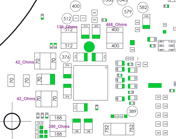
There’s something up with your 1V35PDR (130 ohms) and your 1V8PDR (468 ohms) and is the most likely cause of you excessive battery drain.
Before I provide further diagnostic steps, can you take a photo of this PMIC area of the board, aswell as photos front and back of the board in it’s entirety so I can take a look. Also it might be worthwhile waiting for your replacement fuel gauge to show up and be fitted before I give you the next suggestions also
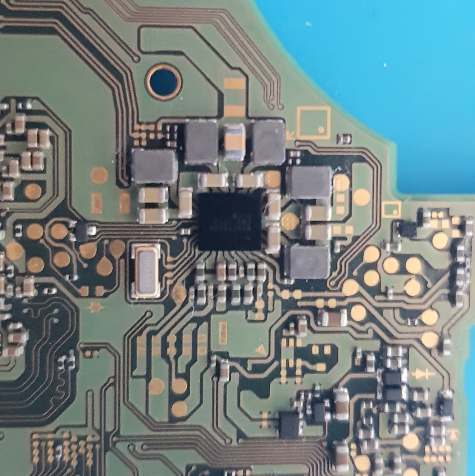
(Assuming the last section of wire is non enameled) Looks to be dangerously close to other lines such as AIN, ground and THERM, I would check resistance from SCL to these other lines and ensure you haven’t got a short or low ohm reading (though I don’t know if this would be the cause of your 1V35PDR short)
If your lacking fine enough enamel wire, you can find incredibly thin stock in old earphone cable
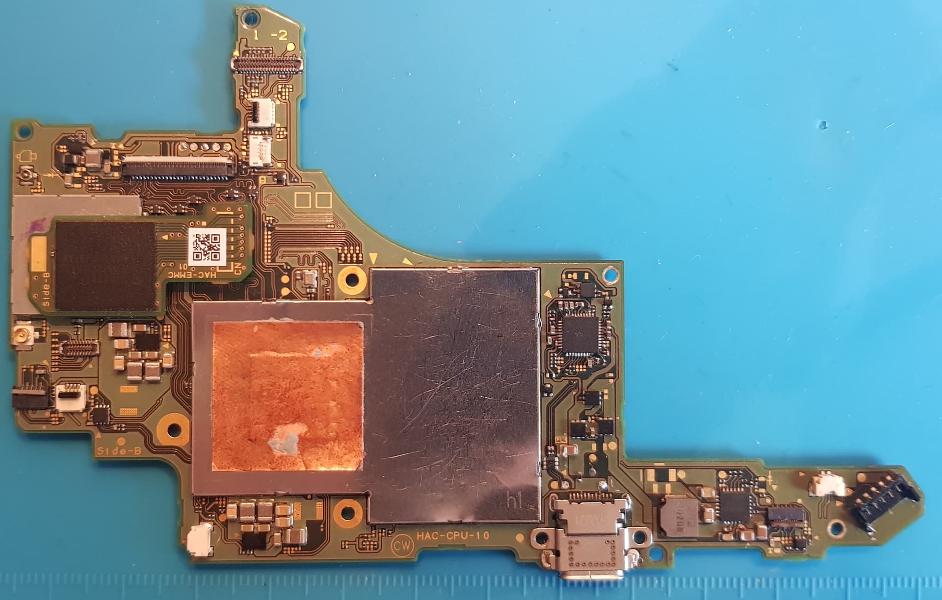
You can remove the two inductors for your 1V35PDR and 1V8PDR and see which side of the pad/s this high short resides on.
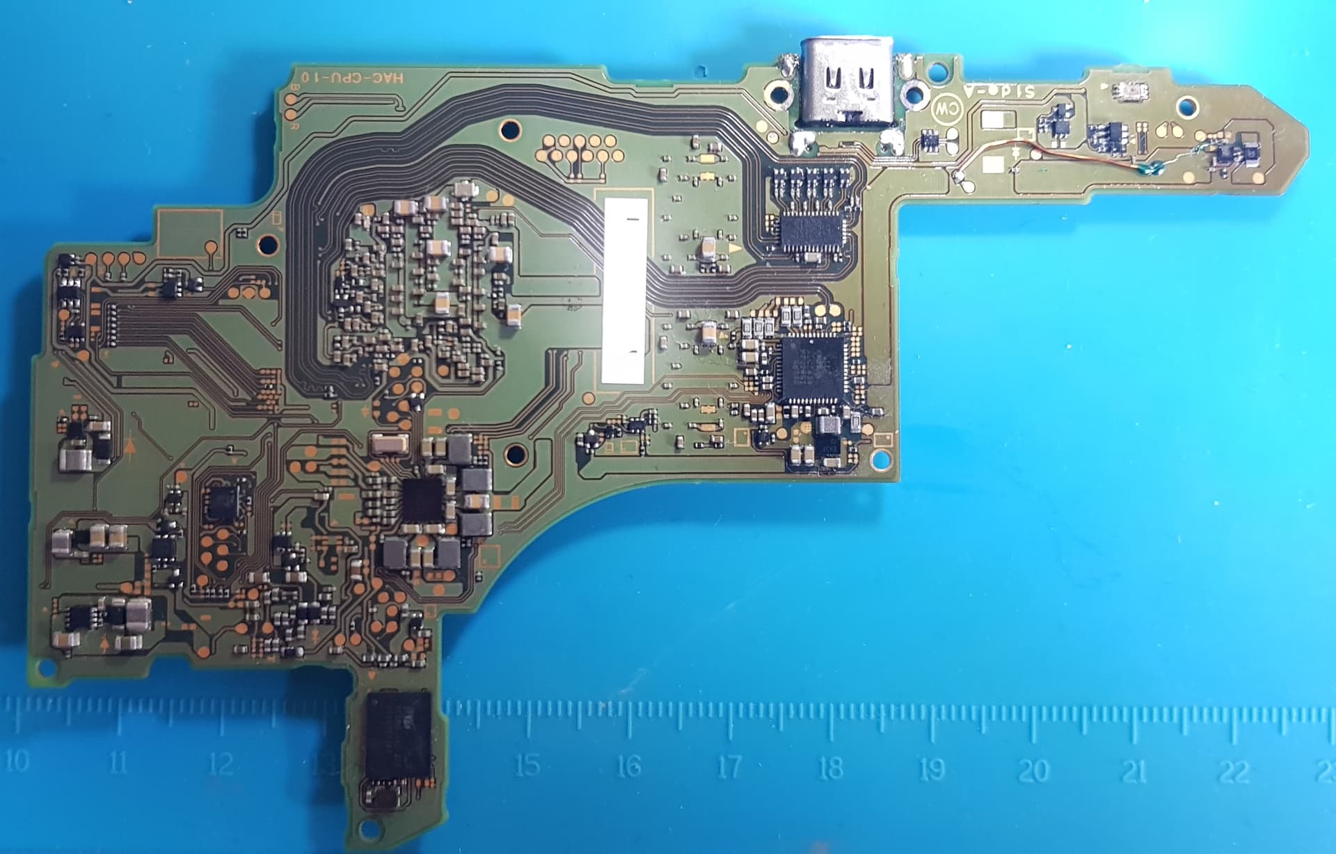
Also as a side note, somebody has removed the SoC shield, dunno if it was you? but if it wasn’t it might be they were looking for a resolution to those to shorts (which could potentially be SoC related)
The thin cable section is the only one that is almost non enameled, I was going to protect it with a mask.
No short with the AIN and between no point around the Max17050, the resistance is 65.5KOhms oddly almost the same resistance as the SDA that I tested in passing.
Very good idea the use of the the earphone cable,
it was me who opened the SoC xxx to test the short circuit on the capcity side of the graphics card, there was one, but I didn’t know if it came from a low capacity or not, in any case I Found a lot of Flux residue accumulating on the RAM side which I happily cleaned up.
There is one cap on the SoC that tests as a short, and is normal
Usually as a result of people pointing there gun towards the shield/ram during M92 rework, the gun should be pointed the opposing direction otherwise it wicks up the shield and makes a mess
Hi mate, not forgotten about your original message to me but haven’t worked on that switch again yet as I’ve had a few more jobs to get done. But nah fuel ic info has never changed, only batter ic info updated to normal values so gonna try a known good fuel gauge now that the SDL/SCL lines are repaired.
Got another question for you though as I’ve come across this a few times and have yet to figure it out. Got a switch here that only charges one way unless the cables being removed. Or it’ll charge .4a both ways till boot and once you take the cable out put it the other way it’ll then only fast charge one side with the other being 0.05a. It’s got a new m92, bq and p13 along with the diode arrays being removed as that can cause only charging one way but a bit stumped if you have any suggestions?
So it’s working up and running thanks to you mate. The missing lines from SDA and SDL were the issue, I just had another bad fuel gauge this entire time despite replacing it several times lol but we sorted now. Learned a ton here!
Hmm I’d probably start by checking continuity from a USB breakout board to the various destinations on the board and rule that out first
The only times those diodes would be a problem is if they failed short to ground, so if neither tests as such you should reinstate them, many a time these diodes have saved an SoC
P13 is a mux IC and has no relation to charge management so will never cause an issue such as this… at least assuming no shorted rail/lines on it would cause the console to wig out as a result, which may be possible I suppose but I think unlikely
I only removed them due to a video from Cod3r mentioning they can go bad without testing bad, he removed them and bam it started charging. I personally had one were that was the same result but you’re not wrong, adding working ones really doesn’t take any time at all and if it can save the SoC then better safe than sorry.
So I actually posted this before I’d taken it out of its shell and I had got it confused with another device I was working on but this one had blown pads on the bottom left 3 of the p13 feeding into the filters/caps. Successfully jumped it but was left with that weird charging issue so my guess is potentially blown line feeding to usb c. I do have a breakout board and didn’t prior to working on these in the past so I’ll give that a check. Just wanted to ask in case there were any other usual suspects.
I see, I haven’t seen this video but the only way I can see this IC preventing other IC’s (which are charge related) from doing there job is if the I/O were bridged together (maybe due to a bad install or failure of the chip) or if there was a short on a key rail which is shared with other charge related components
Yeah open lines is the number one, then the diodes then M92 and then in some rare cases a dodgy fuel guage can cause this strange behaviour
Sorry I misread that, I see your actually talking about the diodes and not the P13
I think the cod3r seems like a nice guy but that statement is complete nonsense if the diodes are bad they’ll test bad, now as I mentioned earlier if he was relying on reverse diode mode measurments instead of resistance (and you’d typically want to test in both polarites here) then a bad one can be easily overlooked
Yeah shoulda specified, the diode array above the usb port on top side and the one to left of usb port on the left side.
This is completely unrelated mate but got a question. So got a monitor here no display due to shorted component. Removed and shorts gone so replaced, powered on and it shorted again. Found out it’s due to a shorted mosfet so removed that and all good so put a new chip back on and I’m waiting on new mosfets.
However in the process the of replacing the chip a 2nd time the material underneath the copper trace on underside of board melted black stuff out and popped the trace off slightly but still in tact and still continuity. Believe it’s a single layered board so should be fine I imagine. Although out of curiosity I plugged the power adapter in with the mosfets removed to see if other things get hot or what happens, well the chip I replaced got extremely hot then blew and I’m wondering, do mosfets help regulate the voltage I take it? And powering it on without it causes excessive voltage to head to that chip?
As I was under the impression mosfets were needed to pass power to the various components. Figured I’d ask you as did a bit of googling and can’t find that specific answer. I also cannot remember the readings now as pretty tired but 1 of the mosfets are good, the other is bad. With the good one off the board, drain to source in resistance I have megaohms which is normal but when on the board it’s more like 500k, just curious if that’s fine or is something else pulling the resistance down on the board. I wish I could remember if the readings were the same on and off the board but I just can’t so hoping to just get some direct advice.
Honestly wish I’d just stopped once I diagnosed the mosfet was the root fault but I just let curiosity get the better of me and wanted to understand things a bit more and it’s just unfurled into a bunch of chaos hahaha.
This is a bit of a tough one to answer bud as Mosfets don’t just serve one purpose and can be used for a variety of reasons… but yes they can be used for regualtion with other discrete components but in order to determine if that is the purpose on your board would require a bit of reverse engineering / poking around
I’m no EE… just some dum dum who fixes things this video will do a far better job of explaining the basic (emphasis on basic here) functionality of a mosfet
and in terms of DC to DC conversion an artcle here
Though as I say, there is far more uses than the two above
Off the top of my head and without knowing more about the circuit this seems fine as 500k is going to have minimal effect on the functioanlity whatever the weather
Haha I understand, I think we’ve all been down this road before
I’m back to give a last news, i change max17050 with balls, dose not change situation : switch still drain battery and freeze each 5sec before response.
Should i remove this inductor? i steel have not stable resistance as showing later.
Which makes sense as you have rails shorted at least two of your primary rails - as for the response issues, are you talking about touch input delay or? as it may be providing a clue, if yes and your reffering to touch issues then disconnect the touch/GC PCB from the board… that all being said, don’t continue to connect power or attempt to power on this console until the issues are resolved
Yes, as I touched on earlier, issues such as these should all be resolved prior to even powering on the device… failure to do so could (or may have already) caused damage elsewhere or in your case potentially cause corruption of EMMC data rendering this whole consol a brick
Also might be worthwhile measuring your resistance to ground on 3V3PDR - which you can find at the large cap near P13 or the two caps near the ENXX IC or pin 6 of M92 etc…
No, because in hekate mode, a switch not freeze and button command or touch pad response normally.
in addition, the information related to the battery drain is false because it does not represent reality. when I restart the switch in hekate mode the battery level starts again from a value higher than what was marked. strange !!