I seem to have a bad habit of bending pins in the LCD connector when working on Switches. I don’t understand why I struggle to remove the ribbon and replace it without bending the pins. They seem so extremely fragile, but when I watch people on youtube do it, they seem to have no problem at all. So a tiny, simple fix becomes a nightmare because now I have to replace the connecter.
Problem is, replacing the connector is an absolute nightmare as well! I do exactly what all the tutorial online say to do. I remove the old one by heating from under the board. I remove the old lead-free solder from the pads. I add very expensive kestor and use quality flux to tin the pads and make it ready for the new connector. I add flux, I put the new connector on, I heat from under, the solder liquifies and I nudge the connector into place. But once it cools and I check the pins, so many are just not connected. There’s no shiny solder attaching it to the board. Some look like they don’t have solder at all even though I prepped the pad. The ones that do have solder, the pin moves with the tiniest bit of force. It seems like the solder is soft and squishy and dull looking. What the heck am I getting wrong here!? I’ve ruined yet another Switch because I can’t seem to figure out how everyone is doing it even though I’m doing the exact same thing. I’m at a point now where I am just so close to calling it quits on electronic repair. I’ve been doing it for almost a decade now and I just don’t seem to have any luck with it. 
Could use some tips or advice as to where I might be going wrong here.
Hello, the good thing about everything is that it seems that you have learned to install the connector well, there are others that damage and cannot even solder the connector, so don’t give up, everything is fine, keep going.
I wish that were true. Currently, there’s no connector on it because the pins don’t seem to solder up. I have one connector left after burning through four of them.
Its a terrible connector design by molex. That being said, the only way to bend these pins is by catching the ribbon under one of them and (emphasis on the and part) you proceed at pushing the connector in, you can feel it, sliding the LCD connector in should take virtually no force (provided there is no flux etc inside the connector) so if you feel any reisistance at all, back the ribbon out and try again. If your still having trouble, “lubricate” the connector with IPA prior. Don’t worry once you’ve done this a few times you’ll get the feel for it, you can even let it self insert most of the way just by pulling it back aligning and letting the force of the ribbons “spring” do the work for you and then seat it home with your finger  As long as you don’t force it, none of the pins will bend.
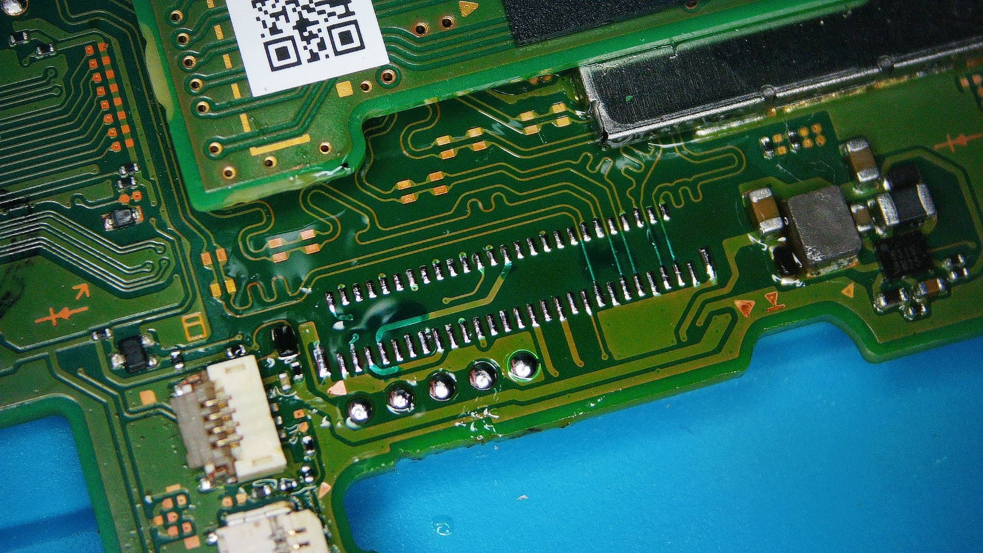
Regarding putting the connector back on. From you image it looks as though your pads a lacking somewhat in terms of solder quantity, try and get them a bit more “puffy” if you can on the board (your solder mask isn’t going to help with this either as it will cause the connector to protrude slightly). If your struggling you can also tin the pins on the actual :LCD connector prior too which helps if they are a little oxidized.that all being said if your two big ground pads on either side have to much solder present then what can happen is they can cause the entire connector to float essentially during or following reflow, so I’d use less than half of what’s present in your image on these two. Regarding nudging the connector, don’t do this, instead you want to align it, then come reflow time, you want to tap the connector downward, the goal is simply to break any surface tension which could hold the connector up and nothing more, be quick and gentle as you don’t want to deform the plastic, this is not like that moronic youtuber who smashed everything down with tweezers come reflow or fiddles with everything come reflow 
Yeah, it’s ruining my life! I swear I’m being as careful as I can be. That’s what makes it so frustrating. I act like I’m defusing a bomb and yet, pins still get bent. I’ll try the lubrication. I can’t tell if it’s happening when I take it out or when I put it in, because I struggle both ways since it just doesn’t come out cleanly. I’ve tried just using my fingers, using tweezers, using a spluger, you name it. Maybe I should be grasping the ribbon from the sides? I’ve been trying to just push on the center to slide it out, but I can’t clear the connector as it hits into the chassis, and then I have to push it as far as I can and try to bend it up. It’s crazy.
I tried adding more solder to the pads, but it just seems like they’ve hit their limit and no matter how much solder I add, it doesn’t take anymore (see linked video - OH, I guess I can’t post youtube links here? Well that sucks. ).
I thought the original solder mask I lost was causing the issue, so I tried to add some, but that just seemed to make it worse, so I tried to scape as much off as I could…this whole thing has been a disaster of me grasping at straws.
Maybe I can record putting the connector on and you guys could give me some critique? Maybe we could identify some flaws in my technique?
Also, when I put the connector on, I should use flux right? I’ve seen some videos that use flux under the connector and some that don’t at all. I usually use flux because that seems like what you should do, but maybe that’s been my downfall?
It’s almost certainly when your putting the ribbon in, it’s near impossible to bend pins on the way out, as mentioned the reason they bend is because the ribbon catches the pin and the force you exert when seating the ribbon is what causes the bend, this is as a result of the poor connector design, usually the “spring” side of the pin contacts are shielded / concealed by the surrounding plastic, molex was like “nah” and left a fair gap… I suppose to be fair, the expectation is for only one insertion in it’s lifetime.
On removal, you can lever it out using the two notch cutouts either side, just working back and forth until it’s removed or you can use two tweezers / spudgers in both notches at the same time, you might be able to pull it out with just your finger pulling on the ribbon (not my preference / never done)
on entry, finger pressure only until your about half way, forget about using your eyes for the most part and instead just use feelovision, pull the ribbon back with your index finger in the middle so you can feel the ribbon is slighty charged like a spring, feel it out, if all is lined up it will want to go in on it’s own with little to no pressure, if you feel resistance then stop, back it out, try again, once it’s semi self inserted which will be approx 50% of the way, then you can send it all the way home using your finger / two notches.
Could be they are at capacity, could be your iron isn’t capable, could even be your using too much flux which can actually hinder in situations like this.
sure, just post the link like > youtube (dot) com/myvideoexyz
Absolutely  I personally go crazy but I have an ultrasonic, so if you don’t you might wanna be a little more sparing otherwise the connector will get gummed up and it’s a pain to clean manually and if it ain’t clean it will make picking up on the stuff I mentioned earlier tricky.
Some awesome tips all around. I will try those things!
youtube (dot) com/ watch?v=Sd2_e8oZD38
Maybe I’m using too much flux!
I will drop the connector this weekend and film it and post back with it. Really appreciate you help.
Yeah perhaps a bit too much flux
Looking at your vid, your iron which is a chisel tip afaict (D24?) might be conducting the heat a little too well together with the excess flux, might be better to use a slightly lower mass tip such as a J-type tip that way the solder prefers to stay on the board instead of getting carried back with the tip. Also as mentioned you probably wanna half the solder on the two big ground pads too which will help
Ok, so I went for it. It didn’t go great. I had to do it a few times, knocked a few components out of place (got them sorted though) and did have a lot of loose pins, but I just went back in with the soldering iron and I think I got them taken care of. Some of the joints seem to be cold solder joints and the solder seems squishy, but I’m not going to mess with it any further in case I just make things worse. I cannot for the life of me figure out why the solder is coming out grey and mushy, but hopefully that does it. This board has been exposed to a lot of heat, so I doubt it’ll work once all is said and done, but we’ll see. Now I just have to put on a BGA chip that got bumped, this is my first time putting a BGA that I reballed myself on, so again, my hopes are not high, but if that goes well, hopefully by the end I’ll have a working system.
Thank you severence for all your help. Keep those fingers crossed for me.
Here’s the joints in case anyone is curios. I know, they don’t look great, but they seem decently solid so I’m just going to have to go with it.
easiest way to install the ribbon, is to do this ribbon fist, when the pcb isnt in the shell.
then place the pcb in the shell and connect everything else.
You are right though, the connector is very feeble, so make sure you connect it square on and you shouldnt have a problem
1 Like
Trust you are not the only one suffering with these connectors. I have replaced a few myself due to bent pins. One thing I don’t think I saw mentioned is tinning the legs of the connector. I think that it helps a lot.
1 Like
I think we are all struggling with that one. Not to mention the tendency for flux to get inside when you replace it.
Don’t worry @Guybrush3pwood , you’ll find your own technique. Mine is making sure the ribbon is sitting flat with a spudger, and THEN slide it in. But I screwed up a few pins prior to that.