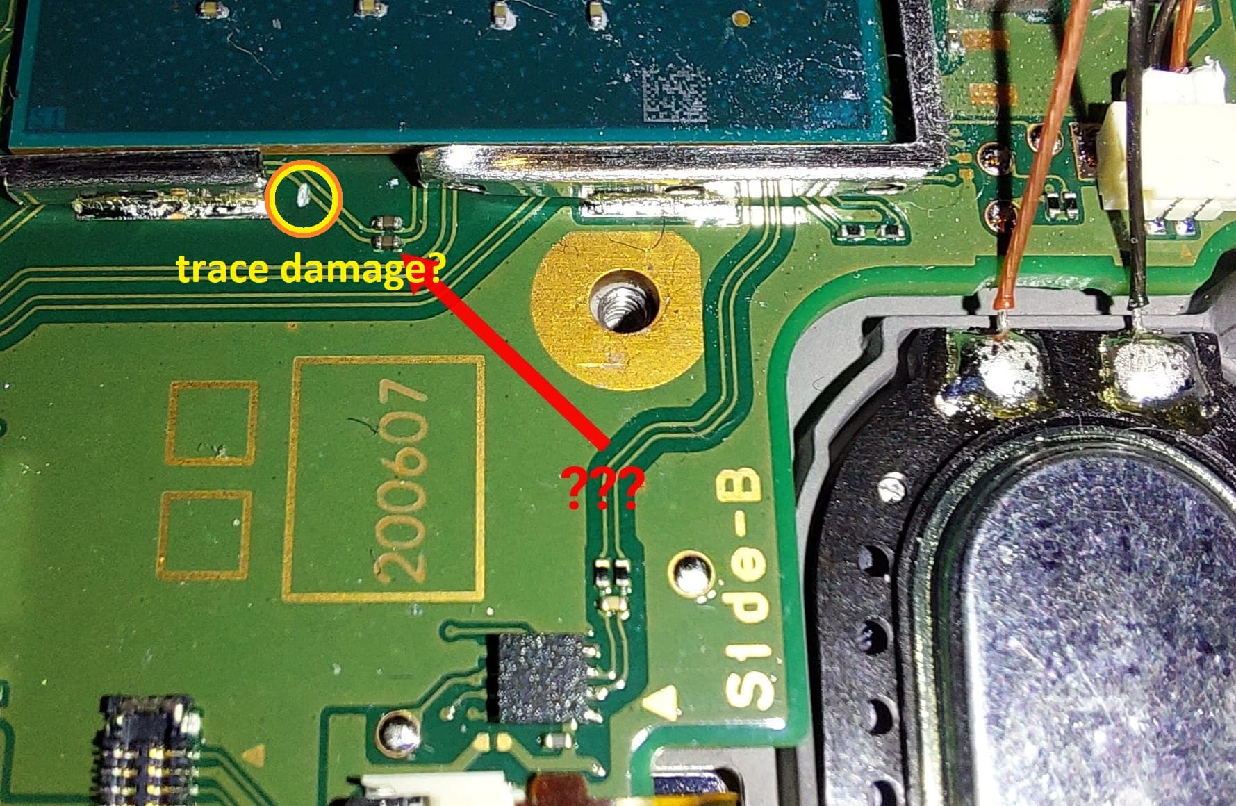
Installing my hwfly ive damaged my switch. Took me a while to narrow down the problem but seems in removing the metal shield from tegra chip I sliced a trace leading to lcd.
And in doing that seems also fried a resistor in that trace.
I can do a bypass with micro wire and resistor but I kinda really need that value.
I measured the one next to it. But I’m getting 427kOhm (or 213kOhm when I switch multimeter +/-) and really thought smd resistor didn’t have polarity… so now I’m even more confused :))
So yeah if anyone can tell me resistor at end of red arrow would be much appreciated
seems I can’t post pictures yet… I’ll try and get back to this
It’s the two parallel resistors directly next to the tegra chip and marking “200607” on the board hope you’ll know which I mean
They are capacitors and the value of these has been posted here on the forum countless times. some people incorectly call them WIFI caps which might be a good search term for you.
Because your measuring in circuit.
afair missing these caps or damage to these caps will typically cause a hang on the second boot logo. So if you aren’t even getting this then you have other issues
Don’t take this the wrong way but if you know someone with a little more experience maybe you should have them do the repair/install or take it to a repair shop
Thanks for your reply. Will check into the cap values then. See if I can find wifi caps.
I get why you recommend I’d go to a repair shop, I’m not offended but my soldering skills are decent enough. And if cap needs replacement I would just remove it from trace and place out in different path with bypass. That I can do. Measuring I still need to learn but only way to learn is trail and error (and asking silly questions on forums :))
I ask because, I noticed a post from @Calvin saying these indeed are caps relating to WIFI (shows how much I know, I was under the impression they weren’t based on people claiming they had no impact on WIFI) but if they are, altering those traces, their lengths or the caps location (drastically) could have a negative impact…somehow…though, wireless board design stuff is a complex subject and I am not really qualified … who knows maybe it won’t make a difference. Regardless I’d repair/resolve your display issues first before moving onto this
Picture is in my original post. Had to get a little creative with link as I’m not allowed to use links or post pictures yet
I wouldn’t care much for wifi anyways… Although if it’s wifi and Bluetooth then I might be a little down as that would mean I’d get problems with joycons later on. But we will see… Like you said first need to get it actually working
That is indeed a huge scratch I was very careless… all me… thought I was awesome having done my oled mod… so was not dismissive about V2 thinking I could just do it just like that…lesson well learned… It did sting a lot, true… But lessons learned and experience gained in problem solving already… Already before fixing it.
Switch will start however… Works fine in docked mode. Just will show blank screen in handheld mode.
But for now I’ll be good and wait for my microscope to arrive before attempting trace fix. In preparation for trace fix was asking for value cause in side nice I get 300ish on one side of the cap and nothing on the other side. Whereas on its close neighbour i get 300ish on both sides. So was positive it was a faulty component (that prob happened due to my damaging trace and turning it on before noticing) least that was my logic…
But then again my logic told me it was a resistor due to its color:) but I’ve been informed it’s a cap
Alright. So cap wasn’t damaged after it seems. Had to be little patient for my microscope to come in… Made a bridge and everything is now working again.
Screen was different issue but that’s been resolved first… wifi was still giving me error codes but after trace bypass and some solder mask cure uv stuff all good now.
Thanks for all your help. Didn’t need to replace the cap but from what I’ve gathered it’s a 201 / 1uf / 6,3v