I have a switch v1 motherboard, the current problem is that the output voltage of the 77620A is 3.4V.
I have removed the SOC and replaced the 77620 for testing, but the problem has not been solved.
Moreover, this voltage also exists when the motherboard is powered on but not turned on. Therefore, I suspect that a certain chip is damaged, and the electricity leaks to this road.
But because there is no complete circuit diagram, it is difficult to troubleshoot.
Do you have any solution? Thank you!
I can’t post pictures. The problem is on the left side of 77620, VDD_CPU_1V0 output by two inductors
Unfortunately if you were measuring 3.4V on the boot CPU rails here then that will have pretty much killed the SoC straight off the bat  I suspect a SYS rail to !V or !V8PDR short is the cause. Might be as a result of the Max IC but could just as easily be quite a few other things on the board… sometimes the original cause i s mangle pins on the USB etc. So in this case it’s not fixable I’m afraid. Just reserve this board as a donor
Yes, I know the SOC is supposed to be dead, but still want to fix this board because I have other SOCs. Where can I measure the cause of the short circuit you mentioned? Thanks!
I personally wouldn’t trust this board again as a full replacement
But, if you want to try and find the cause then I’d suggest searching the forum. First port of call is measuring your “Primary rails” resitance relative to ground, establishing what your boot CPU rails is shorted too (I suspect it will be SYS) in order to narrow down the candidates, inspecting the USB and surrounding support circuitry etc, and checking all other primary rail health in genral, using resistance to ground as a very good indicator.
Hope that helps.
I have tried to measure the voltage drop to ground, but I can’t measure how this voltage comes from. I’ll keep trying to figure it out, thanks~
Not voltage drop bud, rather, resistance to ground (no power connected) if your unsure then search the forum as I’ve covered this more times than I can count 
Locatiion/s of the SYS rail has also been covered many times also and to check for a short from one rail to the other then measure the resistance from your shorted boot CPU rail to SYS with your meter and see what the result is, then do the same again with your other primary rails 
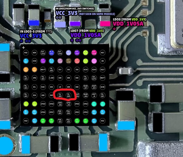
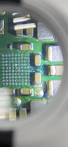
After careful investigation, I found the problem. The MAX77620 chip has two pins FB_SD0, which is the feedback line of the SD0 (1.0V) line. I measured and found that they were disconnected from the 1v0 power supply output. So the voltage is out of control. I pulled a wire to connect them. After measurement, the voltage without cpu becomes 1.8V. I don’t know if this voltage is normal, it seems to be a bit high, maybe because there is no CPU installed. But it must be much more normal than the previous 3.4V.
I also found some serious broken wires on this board, so I gave up on fixing it.
Sorry bud I don’t have a clue what your referencing… maybe something out of a datasheet  this naming convention means virtually nothing to me.
In order for me to help I need you to provide the info I actually asked you for previously, trying random stuff and throwing random tests results around doesn’t help anything 
So, I need you to verify what your restitance to ground is on all your primary rails, then I need you to verify your resistance from one rail to the next, primarily you CPU boot rail relative to SYS then after to your 1V8PDR, then following that from 1V8PDR to your SYS rail and so on and so forth. If any of what I’m saying means nothing to you, then search the forum where I have covered these topics many, many, many, many  times before
Sorry for not being online for a long time. Now that I can post pictures, let me explain.
In this pinout diagram for the 77620, you can see the two FB_SD0 pins I’ve circled. This is SD0, which is the feedback line for the voltage in question.
On normal motherboards, these two pins are connected to the output of SD0, which is just behind the inductor.
But on this board, they are disconnected. So the 77620 can’t regulate the output voltage and the voltage is out of control.
In the second picture, I connected the two points and the output with a thin line. After power on again, the output voltage becomes 1.8V. I’m not sure if the voltage is still a bit high, the possible reason is that I didn’t install the SOC, or it may be because the wire is exposed and interfered.
I gave up trying to fix this board because I found many of the same broken wires. But this problem can also be considered to find the reason.
Thank you!~~~~~~~~~~~~~~

