Nintendo Switch draws 470mA one side on 5v only and boots

Done the reflow (no damage).

use 400°C at 40 flow and when nearest cap nudged, I LEFT HEATING FOR ABOUT 5 MORE SECONDS.
no change, actually it is worse now, it happens more often.

Still got the battery playing around sometimes and dock only works on one side - tested with extensiom.

I am going to give it back semi-repaired, but I wish to know if I can fix the dock part.
Which wiring should I swap? CC1/CC2 = detection

Thanks for all the help, I got the nastiest repair I ever had in decades!

Think that adds further confirmation that the wifi IC is at fault.

would usually be an issue with the inner USB row of pins and/or P13 IC at fault, I would test you have continuity from a USBC breakout board from all USB lines to their destinations

It’d be a bit pointless repairing anything else on this console before repairing the wifi issues as that orange screen is only ever going to get progressively worse until it ulitimately just ends up being either a permanenet orange screen or no boot at all.

Can you provide high res shots front and back of the board, and also closeups of the following areas, M92 IC, BQ IC, Fuel gauge, P13 IC, USB area, battery connector, just incase I spot something out the oridinary

I just closed it up and it has not done it yet and charging, also checked docking via hdmi adaptor and extension though original dock works one side - but customer only use it off the dock.
Customer is moving away in new year and I am not capable to replace WiFi IC. I mainly have done small chips and sockets replacement.

I will try with images,do not hace a high resolution camera on microscope, computer too slow fror it!

I did take some images with my phone thougth microscope earlier on. Will check them out.

Really do not know what to do and I am shocked I am in this silly situation and bothering you guys with it.

Here are images, I hope decent enough … and to think I have an Astro-camera and I could not use it as this PC is ooooold - if I can, I will get a used WIN10 with decent graphic card! I prefer to work with camera watching TV rather than microscope or both.

I also could not use a DSLR - too high and in the middle - will need a flat cam with HDMI when I can afford it + second hand PC.

Thanks to your input, I found I did not fit and maybe destroyed the 17050 - I was down that day… and must have missed it - i hope that fixes the battery percentage etc.
What you see now is a newer fit and added a new capacitor too, received today.

Today I worked at lower temp and flow - I think was 250-260°C and 35 flow - small chip!
Tomorrow will test it again.

Please note, the soldering around chips have been probed thousands of time to ascertain DIODE mode and Voltages supplied by the always helpful Calvin diagrams.
They look worse than they hopefully are.

I did not find anything strange, all measurements were slightly off, due to meter - all of them.

Now I am going home to fit new (low cost) arrived TV, so grandson will be happy.
Although we do not push him to watch much TV, we all tend to play with him.

Might be a future technician of some sort as he is interested (at 4 years old!) to see how things work.
I get a car or anything else towards my head and say: Hellooooo!
He says … THAT is NOT a phone!
hahahahah


That TV made me waste 3.5 hours and then I re-packed it for return.
What a load of rubbish.
This time I will do what ‘I’ say and get a decent TV without breaking the Bank …

Will now try the Switch ‘again’ for the 70th time … with a decent 17050 fit + cap.
Pfff

I finally discovered, apart from the obvious faults ‘anyone’ can fix, when you get a ‘serious’ problem, these Switch are like any other device … a nightmare and a DAY-mare!.. if you do not have full self-training!
What have I got myself into … in my last few years before retirement …

  1. Re-done 17050 ‘properly’
  2. re-done Wi-Fi chip reflow
  3. checked PI3USB based on Calvins schematic and checks OK, I also did check voltages last time - all OK
  4. Now I am rechecking USB-c connection. I scribbled my own schematic after checking ‘several’ times the sliced PCB and I believe they are correct - in fact it does charge both sides slow and fast since then.
    But every time I check ‘other’ schematics they are ‘all’ different!

Upon cheking Calvin PI3USB Diode mode + voltages schematic, I just noticed his filters/USB-c connections and they are different from mine!

This USB-C schematic seems a pestilence!

I am sure mine are OK, but will ‘only’ re-check PI3USB data and compare to mine. If wrong, I will have to change - what a wasted numbers of hours!

Just confirming I checked my scribbled schematic and PI3USB chip datasheet and they are the same - exactly.
mmm

I am doing all checks before I re-fit and test - to save time hahahahaha

Even more confused now - on this USB-C onnections - Datasheet wrong?

Sorry for that. My fault, I mixed two things up by only looking at the naming at the pi3usb datasheet: SBU1/SBU2 and TX2/RX2 are swapped. I double checked it now with the layer view and here is a corrected version: Now the pad names correspond to my usb c pad names.

No problem Calvin, you always do a great job helpuing others, we all make mistakes and in this case it is confusing!
I kind of redrawn my connections and re-done mainly the hidden USBC ans a couple of on the other side.
I believe now it is correct and matches yours.
I will do other checks and then re-fit and finger crossed I get the right connection and end this part of it.
It is all to get TX and RX + SBU correct side. The rest is usually easy.

Your better off checking for continuity at the USBC connector, diode/resistance readings relative to ground are a good quick and dirty check but they only give you 50% of the picture and a line which is oridinarily open (relative to ground) in one polarity may not actually be open in the reverse poarity etc etc or you may have a line incorrectly connected which you won’t see in diode/resistance relative to ground

If you have a USB C breakout board check for continuity to the following points instead (albeit from the breakout board instead of USB pads)

There a few potential issues I can see from your images, I will be back at some point to highlight them

As mentioned earlier, your putting in a whole lot of work for something which is ultimately going to end up in a permnent orange screen state, stuck at second boot logo or black screen no boot due to the wifi IC. You can pick this IC up preballed from somewhere like zedlabz (note if you get it anywhere else you have to ensure it’s preprogrammed for Switch specifically) then all you’d have to do is pull the existing IC and wick the pads, alternatively it might be better off to send this one off to another tech if your unsure if you can do it :slight_smile:

Yes, I did and do the resistance check from breakout board to filters etc. - force of habit in my career on other repairs - totally agree.

  1. DOCK PROBLEM SOLVED
    I might have mixed tx rx sbu on the hidden pads as now I re-fit and it does dock fine and on my old TV too.

  2. CHARGING and Battery
    I have docked it to see what happens, it is charging OK now - will have to see discharging too when at 100% - almost there
    I am actually confident, battery problem might be OK now, as when I docked it it stated ~ 87% and the battery last time I measured it was 4.04 I think - so about right if we consider 4.2 full

  3. the Wi-Fi ‘thing’
    I did re-flow once again - possibly better than last time
    But … it did take 4-5 reboots to boot normal!

I do not know anybody in UK I can be ‘sure’ is a good tech - at least better than me (!) to fix the Wi-Fi thing without breaking the Bank.

Know anyone?

‘Finger crossed’

I’d go ahead and replace all highlighted passives with discoloured/damaged endcaps, if you see any more dotted around the board which look similar just go ahead and replace them as it’s not worth the aggro (even if they test fine in circuit)


Sorry no, hoping someone will pop along and offer, if not worst case you can send to me and I’ll do it, but as it’s been worked on prior I can’t guarantee the repair, I’d also (and please don’t take any offsense here :open_mouth: ) I’d have to redo your USB install

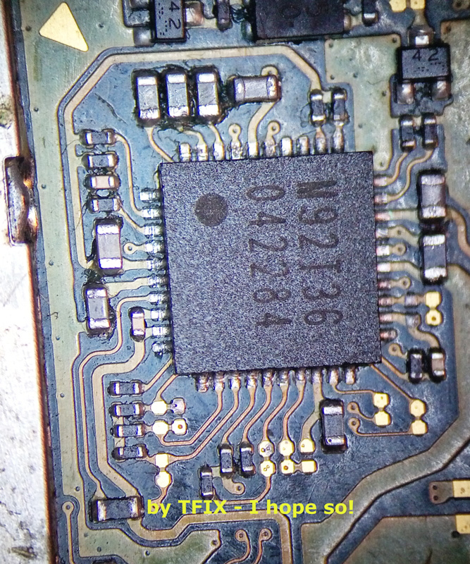
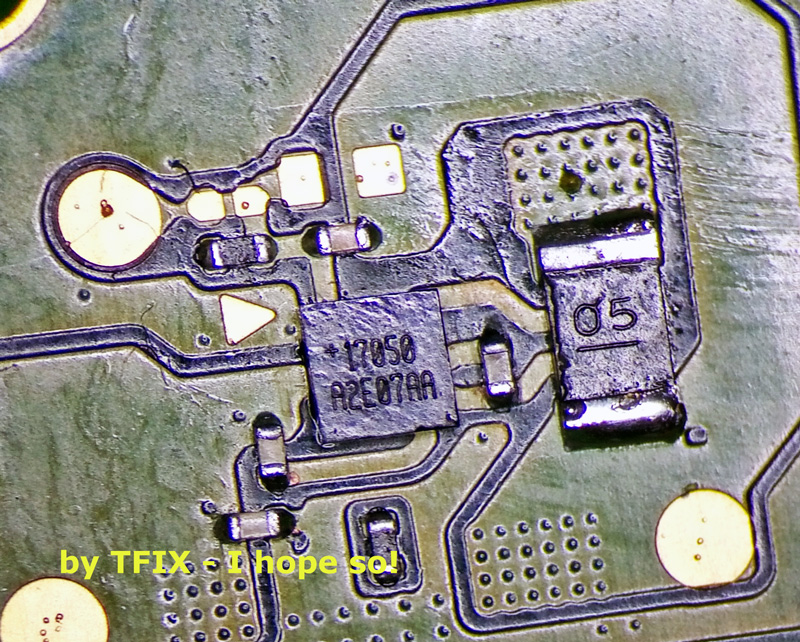
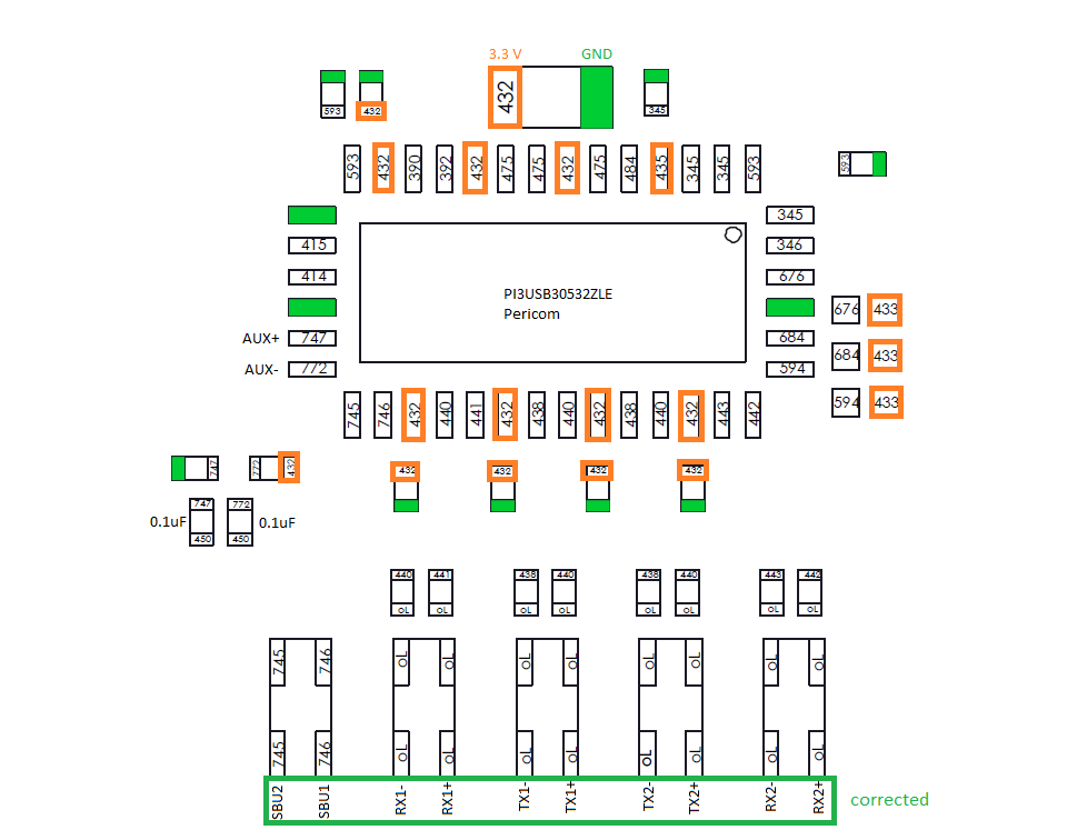
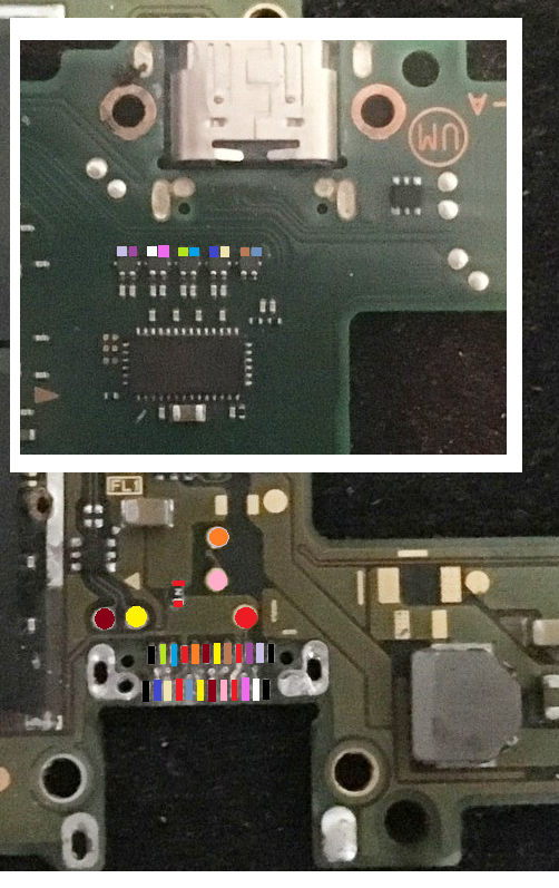
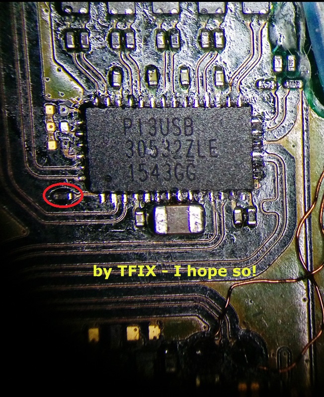
I will check those passives, but I am sure just maybe the one near PI3USB and maybe another - I think I did measure al lot of them - but of course they may misbehave when under load.

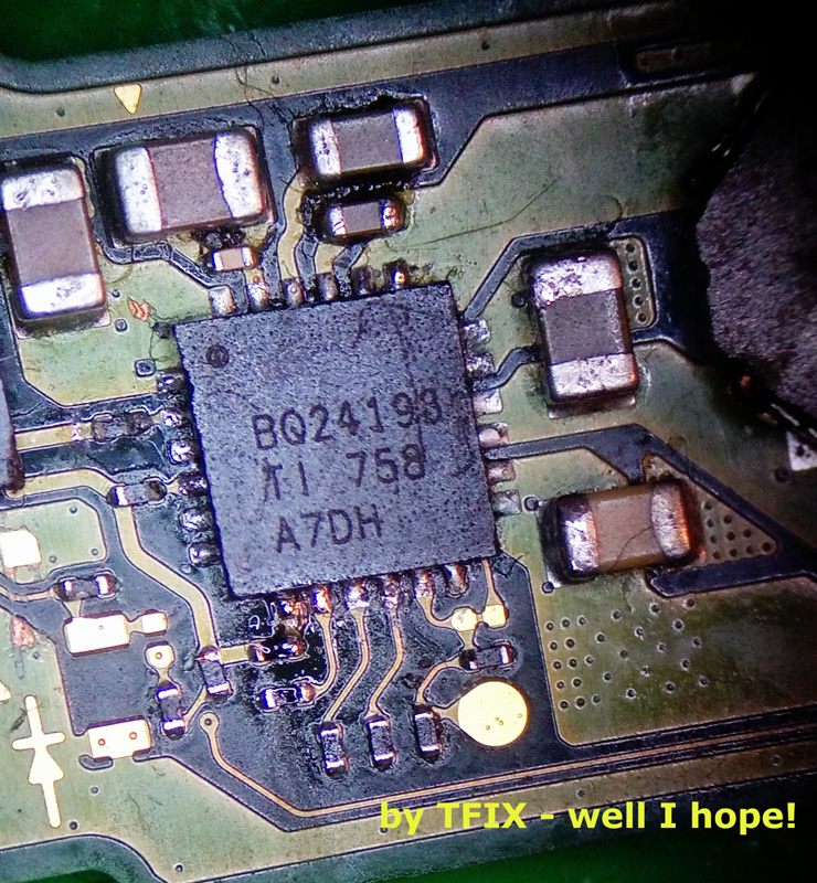
Most of the discolouration is probably the flux, which is not the best one (Kingbo) and I would have put it in a Sonic Bath - I have a cheap one for small PCBs and by holding it with my hand to avoid soaking the CPU!

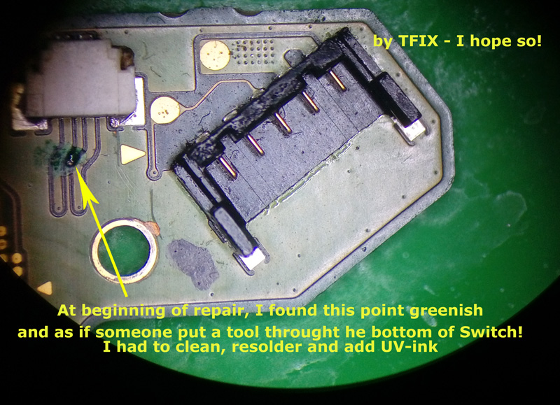
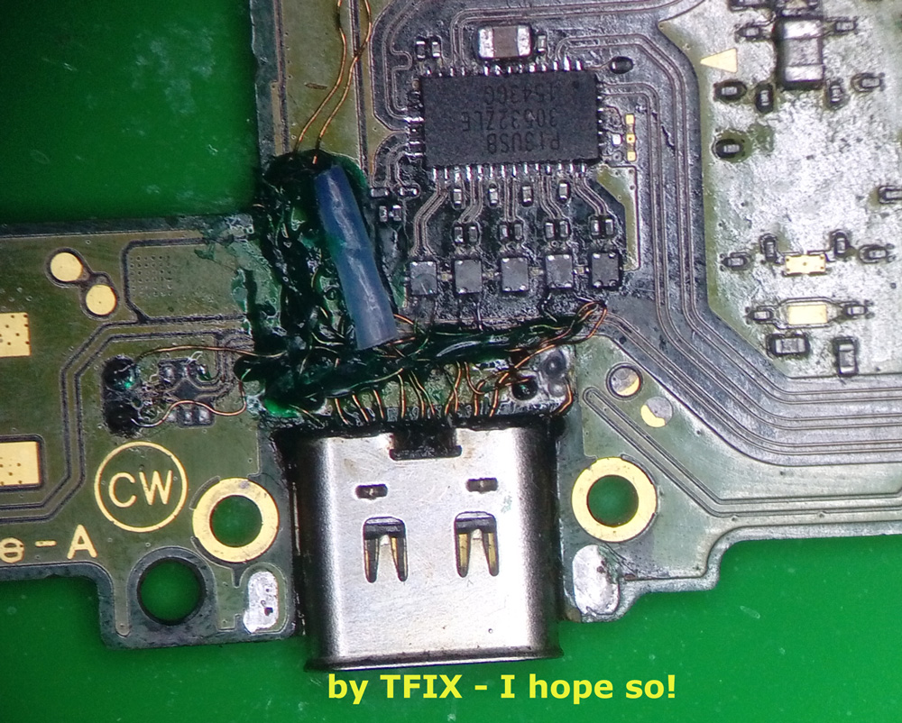
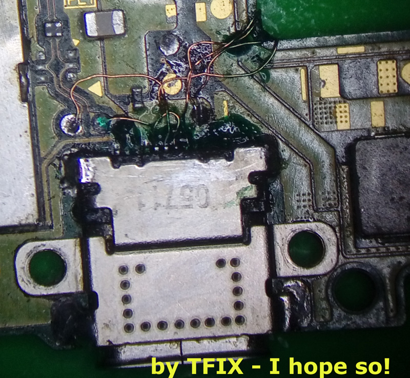
I already did a clean-up half way and I also did replace the port and re-wired it once and it was nicely done, as mentioned above, it looked a mess because I had to put my hand on it several times. It is all connected from external break-out board to end of wire on PCB - since I re-fit it never had a disconnection, but now looks like Hiroshima - as Northridgefix would say! :rofl: :joy:

I would have done it again, although wiring is fine (!) and problem was only the ‘finally’ found correct connection of the underside pads and not the port itself, as second time I did use some UV-ink to lock the wiring and there was only one I had to join it externally as it snapped because I did not notice the wire had a ‘pre-cut’ on it.

Yes it is a mess now and the main reason it looks a mess, because it has become one, due to the incorrect wiring.
It always is the ‘first’ of my work - this one was for learning and I normally find ‘my way’ of doing things properly.

I used to work in telecommunications devices (mainly) on component level and done so many racks and the internal 10,000 wires in it, and the boss had chosen me because I was the one meticulous enough to be able to o a good and ‘safe’ job - always been, whatever I do. Especially when I worked as Technician for a Company doing harbour mathematical models - I loved that. Just treating the harbour in a few weeks, as if it had the sea battering it for 10 years!
I see how other do things I do not know, I learn and find a better and cleaner way of doing it - including my own drawings.
I applaud Calvin with the drawings as we probably think alike - in that sense - I do not like mess, but I am in a mess at present - I am even half way re-laying out my workshop - with main bench being micro-devices. One must do some drawings and measurement on a new device, which then will become second nature as with Calvin and Severence!

Now micro-technology I did not manage to get into about 10-12 years ago - for personal reason I could not do it - missed that boat.

Merry Christmas or not (if you are not bothered about it)… I am just following the herd these days … a little bit. Last 3 years had not a usual stupid Christmas.

… I might start doing repairs via website and shut shop for ‘human’ interaction for good.
So, I can concentrate on repairs rather listening to banters all day and waste valuable time…
Locals have never been loyal over here, apart from the usual that knew us already and trusted us, and those - which these days are 60% of the work - that come from other areas and come back, once they find we do a good job and give back ‘the whole’ device!

These days I do a bit of everything, after I missed the boat and do iPhones ‘basic’ repairs (not PCB) and I have to say 7 out of 10 I get, there is always missing parts or screws flying around (they were prior repaired)!

The worst one was an iPhone 7 - if not wrong - with NO shields at all and its screws ! Imagine screen getting hot over the battery!!!
Another similar but still had screen shield, but they left the plastic THICK film on it - imagine the screen instead getting hotter.
Screens replaced and they never cloned data from original screen + replaced button after they snapped flex.
I could be talking about it for weeks.
I am not better than them, they are worse than average - most are not even average!
They actually only care to get their $$$ £££.

Going now …

Yeah, it’s best just to replace them and be done with it, if it’s an aggresive flux (or too high heat in combination) which has caused this, then all the more reason to replace :slight_smile:

It wasn’t a criticism, I’d just have to redo it as premptive measure, chances are the VIA nubs are still intact (they always are) which makes pad repair possible, these are high speed lines, line length matched with strategically placed grounds lines/planes, as your lines are no longer length matched and are all crossing each other it will increase noise, chances are it will work fine and for the foreseeable but I don’t know (for example in these cases) what dock the customer is using or how cheap their HDMI lead is or TV etc any of which could change/alter signal to noise ratio and prevent something from working outside of my setup, so from experience it’s easier to take care of all these problems in one fell swoop :slight_smile:

That, and I would be putting it in my large ultrasonic and it makes it easier to clean if there isn’t wires everywhere :smiley:

1 Like

No problems and no offence, of course - I would do that too - it makes you a good technician, I was just saying it as it is.
I understand that too, in fact I was going to test using either using flat cable or simply working the pads a better way.
The first time I did it I repaired the pads and only one was not connected.
When I repair, but also with anything I touch, I do care and I am normally a tidy repairer and this Switch has been so over-worked being also ‘the’ learning one.
:+1:

I will have to wait to see what customer say, as he is going to move from here (good for him!).

How would I go on about sending to you, ‘if’ customer agrees etc. - I do not see any way to direct message on this forums.

Maybe it is me that does not see it… sometime one needs a direct contact, for many reasons such as Privacy and Security… mainly.

The first switch I fixed is my kids, and I did the USB-C like you have, with everything manually wired.
It charges fine, but docking it is complete luck, as sometimes it works, and other times it just outputs a black screen. Even when it does work it often refuse to play youtube videos, presumably because it fails the HDCP handshake.
I have plans to go in again and fix the pads rather than wiring it, but that would mean him not having a switch for a bit and its hard to find a good time to do that!

1 Like