I got an Nintendo Switch from a customer with no video on dock. Switch works other than that fine. I tried the following things already:
Check USB-C port, no problems found. Charging on both sides.
Check for shorts near P13USB - no shorts found
Check the chokes for continuity - all fine.
Replaced P13USB - tried 2 different IC’s from 2 suppliers.
Still no video.
diode readings of USB-C breakout board:
A12 .000
A11 OL
A10 OL
A09 .472
A08 .476
A07 .743
A06 .753
A05 .646
A04 .471
A03 OL
A02 OL
A01 .000
B12 .000
B11 OL
B10 OL
B09 . 471
B08 .474
B07 .759
B06 .759
B05 .699
B04 .472
I don’t know what to do anymore. What should i try next?
Very interested to know if you work this out, my kids personal switch is like this, it will connect occasionally and display (maybe once every… 30 times put in the dock or so), but will will usually fail an HDCP check on YouTube. The original port fix was dubious (fully re-wired with jumpers) so I always assumed it was that, but having redone it I no longer think its the case, but clearly something is unhappy. The only thing that comes to mind is high resistance on one or some of the lines, maybe from via damage or something?
I dont have any of my stuff set up currently to check board here (just moved house), but will do so once I am if you haven’t worked it out by then. Do you have another board to compare against?
check for actually continuity from a USB breakout board instead of diode mode readings… diode mode readings at best only give you 50% of the picture,. If your meter has an ohm readout while in continuity mode ensure that all lines measure approx < 3 ohm (minus your leads) point to point, it’s typical on boards which have been over reworked that the vias separate and the lines become partially open or intermittent, so you also want to ensure that the readings don’t alter (at least in any meaningful way) while probing which would be a good indication of this, particulary at the filters.
If you meters continuity mode doesn’t show ohms then instead put your meter in resistance mode and use that instead.
Insomniac I expect you probably have a similar issue, or that your jumpers are of too inequal lengths and/or are crossing
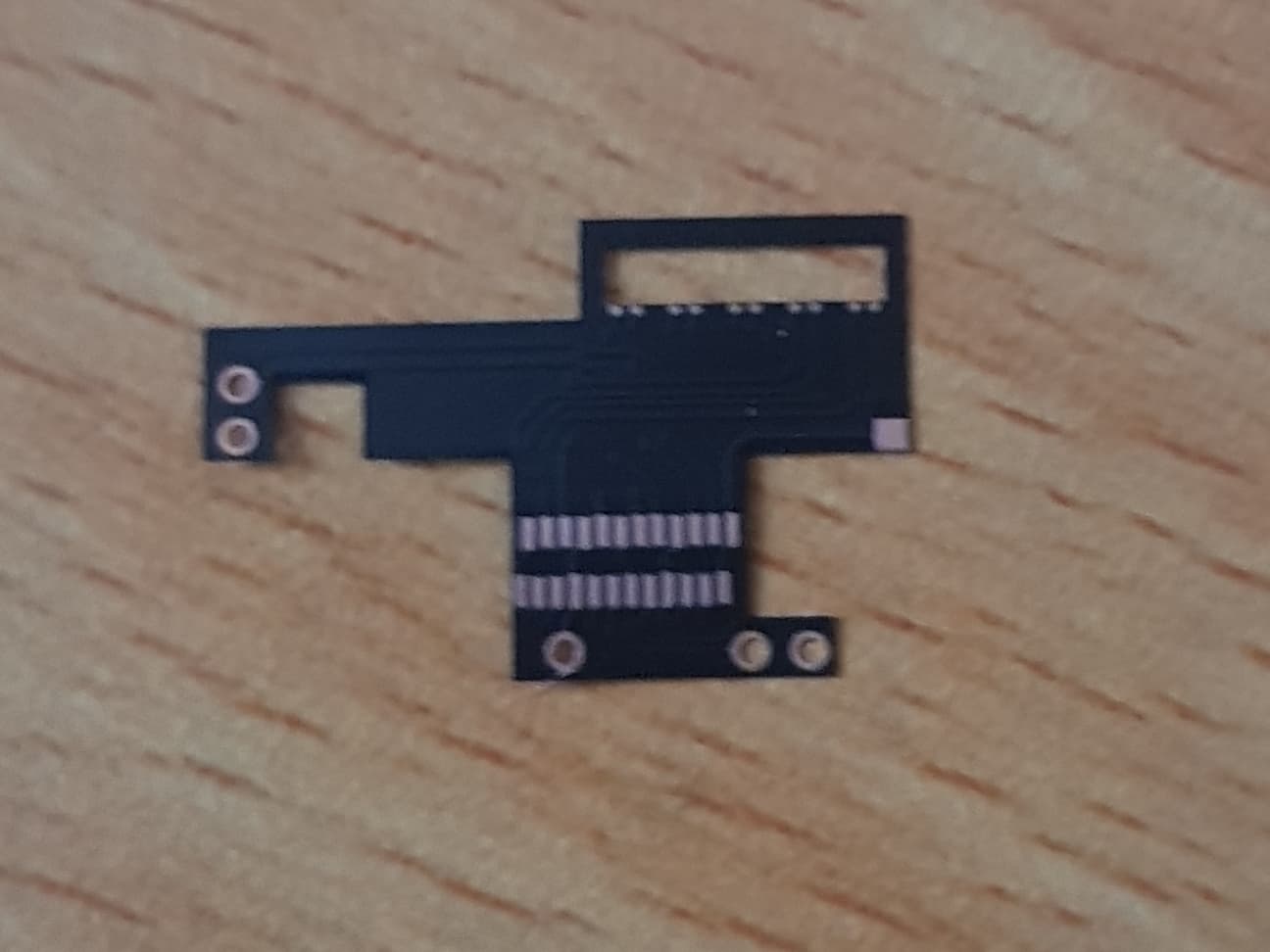
My end that was my original thought, which is why I changed it out for one of those flexible pcb things to restore the pads, that should also bypass any bad vias. I was expecting at least some improvement doing so, but it didnt change.
I am reluctant to go poking at it though, as its always in use… maybe it is a dodgy filter or PI3 at this stage…
I don’t think I’ve seen these, can you show a photo if you’ve got one? also did you take a snap of the board after you worked on it? might be worthwhile taking a peek and see if anything jumps out
Could well be, the filters used here have incredily weak “legs” which seem to be really poorly bonded to the ferrite, I’ve had situations where I’ve hand soldered on a new one and the leg begins to detach (upper portion, which is almost paper thin) and have to repeat the process, this results in similar symptoms as I mentioned above with the vias, you’ll get intemittent or low opens or just completely open
It’s also worth noting that aside from the P13 lines there is a whole bunch of other inner lines making there way to/from SoC, M92, p13 etc which can fail open in a similar fashion which could also result in no dock if in failure which is pretty much unrepairable without a board swap
Found the problem. It was the dock. Tried with another dock and it’s working like a charm. The strange thing is that another Switch works with the dock.