Hi!
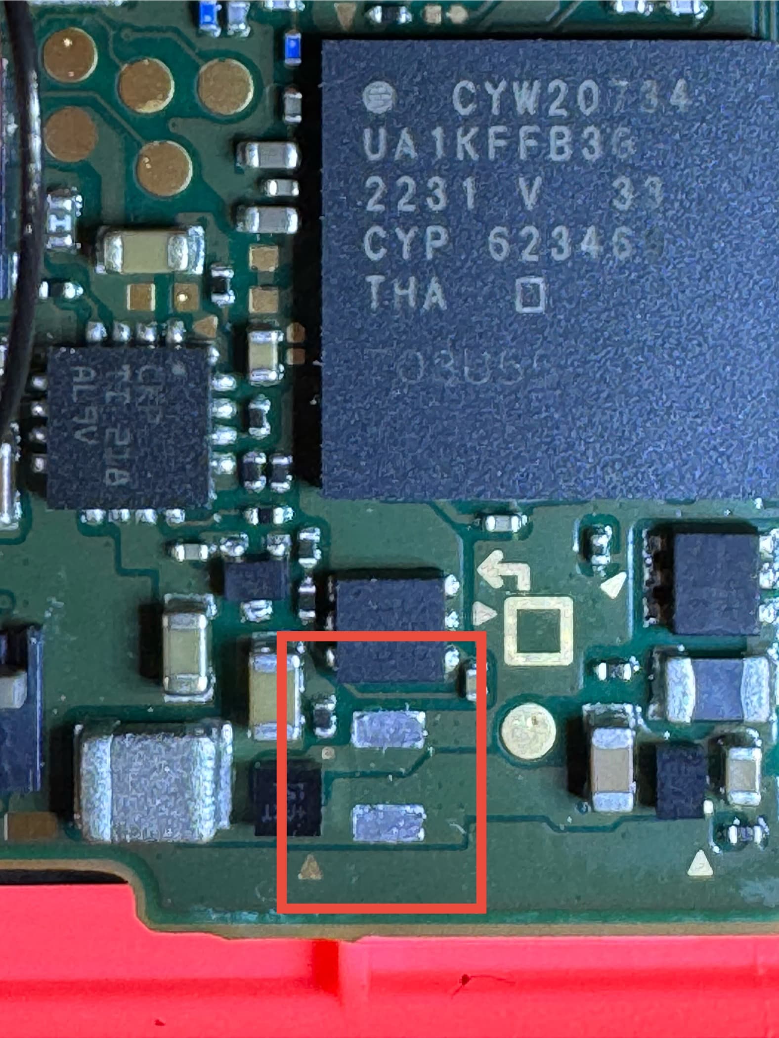
I bought a pair of broken joycons, and the right one is especially heavily damaged - it’s not connecting wirelessly (although it has power, since the LEDs are showing the sync sequence), the top case is broken, analog’s button is not working, the R button is broken in half, its microswitch is ripped out of the board together with all three pads, the rumble motor has the metal casing slightly bent in one place, and there is one component missing on the board. It was present inside when I opened it the first time, but I guess I flicked it with the tweezers and sent to its happy place - can’t find it anywhere now.
So I’m looking around the web what it might be, but can’t find any schematics of that area. Does anyone have an idea?