So this one has me perplexed. Hoping somebody here might be able to help.
The Switch in question had BSOD. I reflowed the main chip and the memory chips and that seemed to have fixed the issue. It turns on and appears to function as normal. However, it just refuses to display on my TV when docked. I have other switches and they all dock just fine, so I know it’s not the dock. Here’s what I found when troubleshooting.
PU13 has no shorts on any of its caps. Neither does the M92 or the BQ.
I checked all five filters under the PU chip, all appear to be good.
Since I wasn’t finding any shorts around the PU or anywhere else and since the filters seemed good, I decided to replace the USB-C port. While it didn’t look horrible, it didn’t look great either, so I figured that might be my culprit. Nope, still no display.
I plugged a breakout board into the USB-C and tested the contacts between the breakout and the filters and all were making connections to where they should have been.
So at this point, I’m out of ideas. I figure I could reflow the PU IC, but after doing the BSOD fix and the USB-C port, I’m hesitant to apply anymore heat to this board. Any thoughts as to what else it might be?
Decided to just go for it and replace the PU13 IC. Still no image on the screen. I can see some of the traces going from the PU13 to the main chip, so while my reflow worked on getting the system on, I’m guessing maybe the solder balls directly related to the PU13 didn’t make a connection.
So now the question is, do I cut my losses and be glad it works in handheld mode at all or do I try a second reflow, risking killing it for good? Decisions, decisions.
Hi,
Okay, did you measure the pins in diode mode and have all pins a value? If yes, the chip is soldered correctly. To check the connection to the apu, you can also desolder the pi3 chip and measure again.
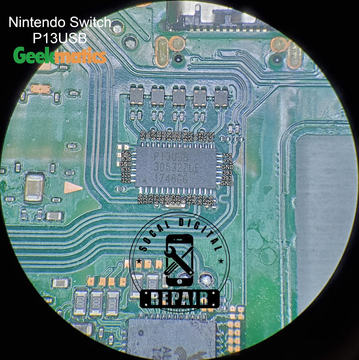
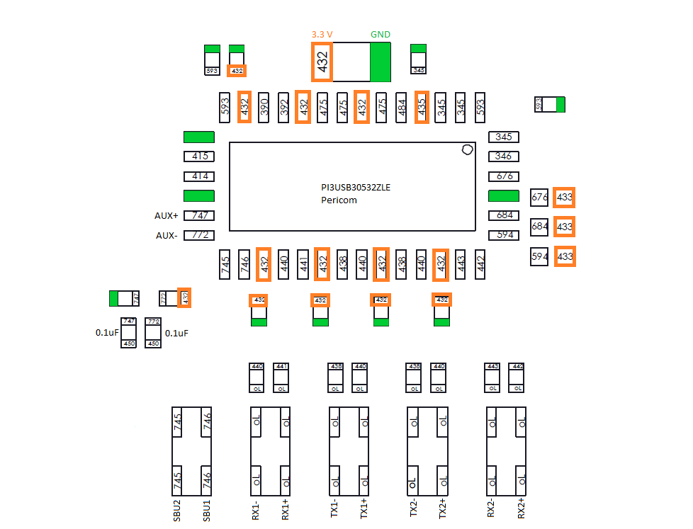
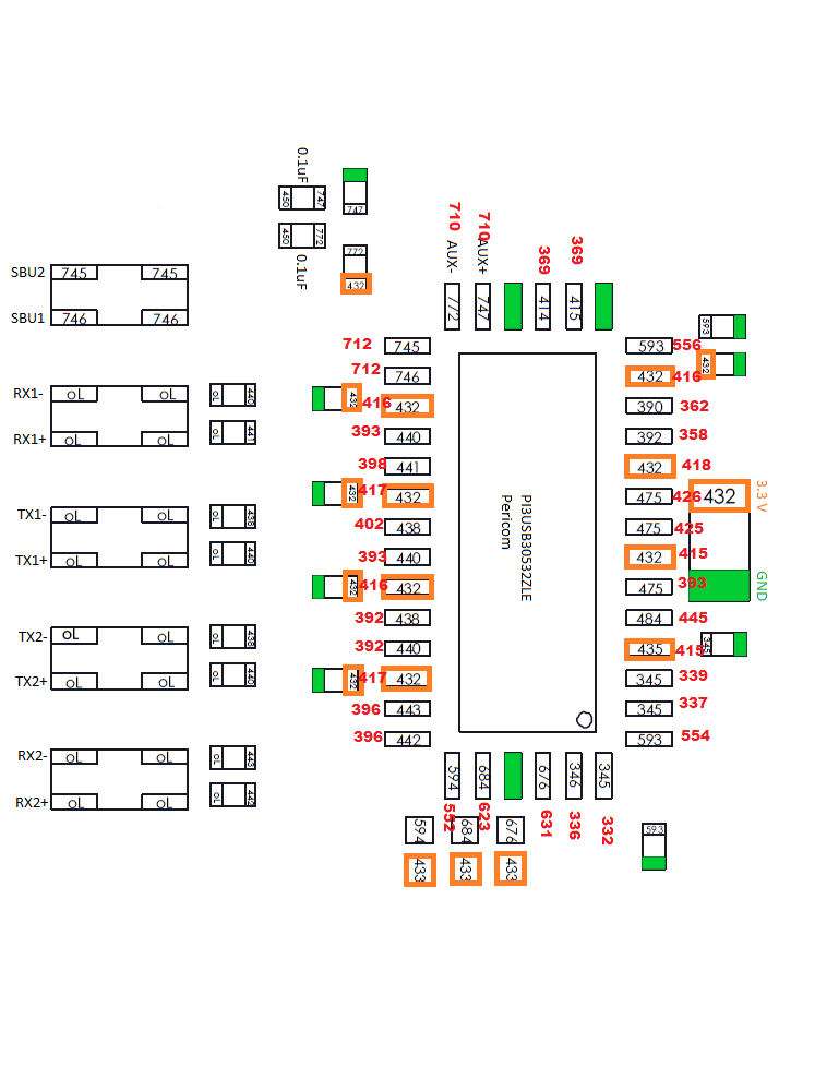
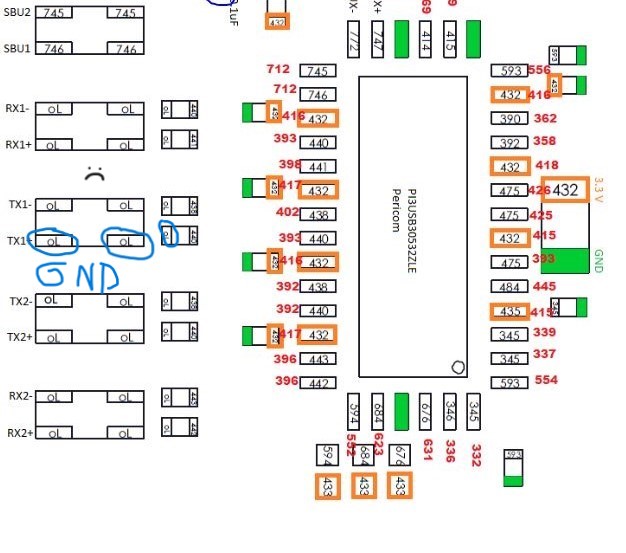
Ok, I went around and I THINK it’s mostly good, however, using this as a guide, I find I’m getting in the 400 range on the pins that say OL. That doesn’t seem right…right? Otherwise my readings were close to the numbers seen in that photo.
My readings in red. Some started higher and then slowly dropped. I recorded the number it seemed to finally settle on. Everything looks lower than it should be…not a ton lower, but lower none-the-less.
The readings in diode mode depends on the multimeter you use. The readings seems to be fine. I would change the pi3usb, if everything else (filters and port) is ok.
If you changed it already, I would check the soldering on the pads around the pi3usb. The readings of the input side of this ic could read fine, but have no good connection to the ic.
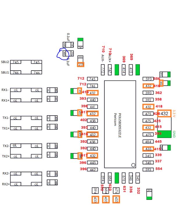
I think I found the issue. The cap circled in blue was giving me OL instead of a 450 reading. I removed the cap and touched to the pad, same deal, OL instead of 450. I’m guessing that’s probably the issue. That cap seems to go to a resistor under the main IC. Soooooo…I think that this point, I’m calling it quits. I’ve invested too much time as it is. I’ll either sell it for parts, keep it for testing or just give it to some kid who can play it in handheld mode.
If the whole line is fine, no scratches or any signs of damage and the both 100k resistors on the end are also ok, the issue probably is the SoC or the bga conntact.
So i have similar problem but this side of filter is grounded and this thing too.
Everything else should be ok. And problem is switch charging only one side
I’ve seen switches charge only on one side for two reasons.
If you replaced the port, not all the pins are connected.
M92 chip. Even if you aren’t getting any shorts, I’ve seen a faulty M92 only charge on one side. I replaced the charging port at least 10 tens, thinking I was going crazy. Then I decided to try changing the M92 and bam, would charge on both sides.
If one of the filter is shorted to ground, remove first the part. If one points still gnd check your usb c port. All these points are connected to usb c.