Good morning
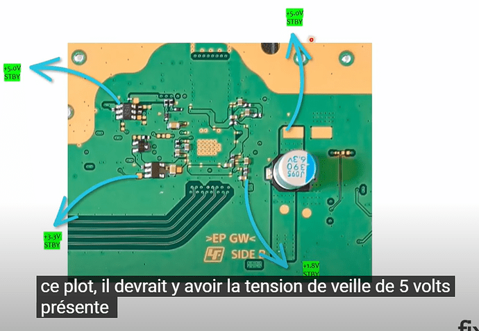
I have a question: I am missing on an edm010 the 2 voltages 3.3V and 1,8V stand by from the image if attached. Can anyone tell me where it comes from? For me these are the ones linked to Mn864739, but is he the one who created them?
THANKS
Mn864739 is HDMI encoder chip, and it uses 1.8v for the data line but it does not create 1.8v or 5v.
5v standby generates from TPS53219A next to Mn864739 on F7001, and 1.8v standby generates from TLV62090 next to southbridge(on the back-side of f7002)
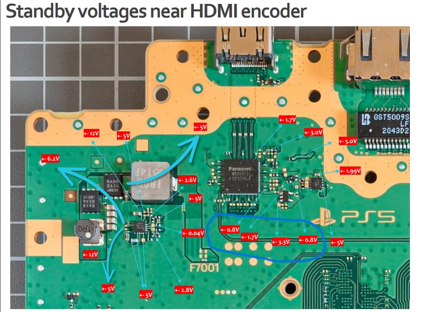
thank you so if I don’t have these 2 tensions it doesn’t come from MN. But I do have the 1.8v which comes from the TPS53219A so why don’t I have these 2 voltages 3.3v and 1.8V. In this other image, I am also missing the tensions circled in blue, where do they come from? It seems that they are linked to that of the other image.
you have yourself explained. You dont have 3.3v or 1.8v therefore you wont have those 0.8v or 1.7v near Mn864739.
Instead of measuring around, you should focus on what standby voltage you missing(3,3v) and find out if any of them short /low resistance to ground
Thank you, but I don’t have a short circuit on any 3.3v or 1.8v line, so my question is where do they come from? Or are these tensions only present on certain versions?
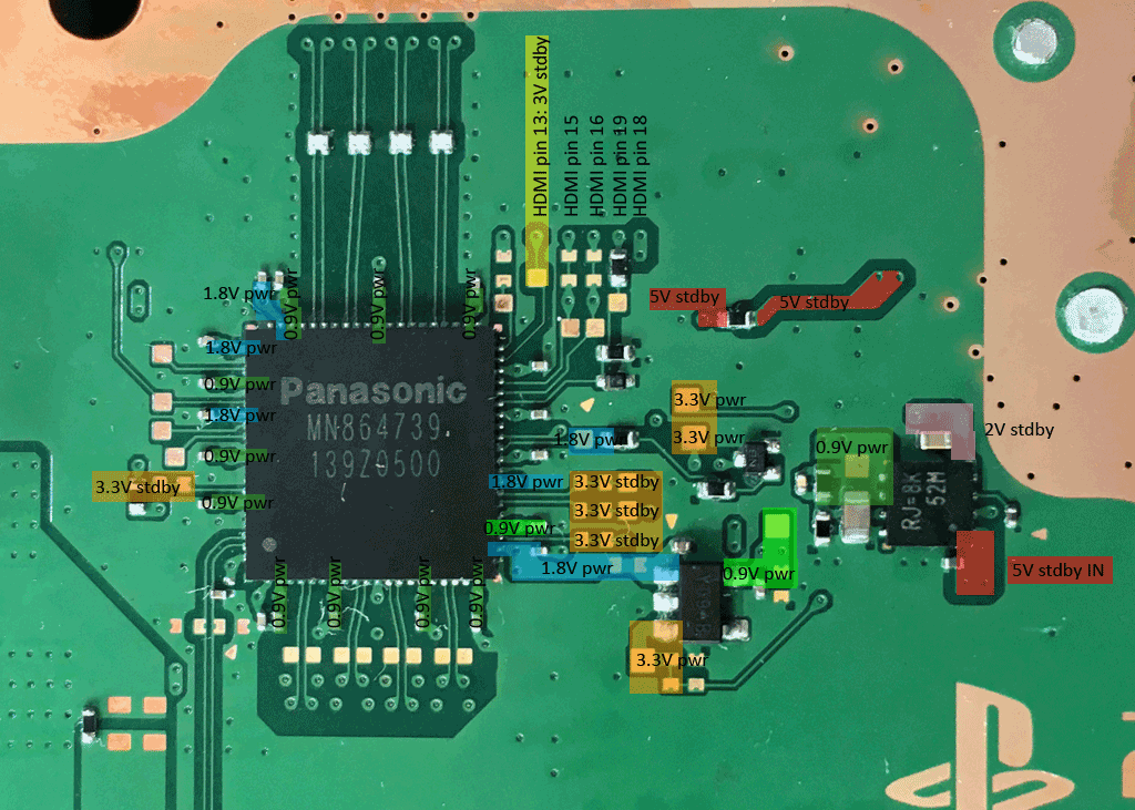
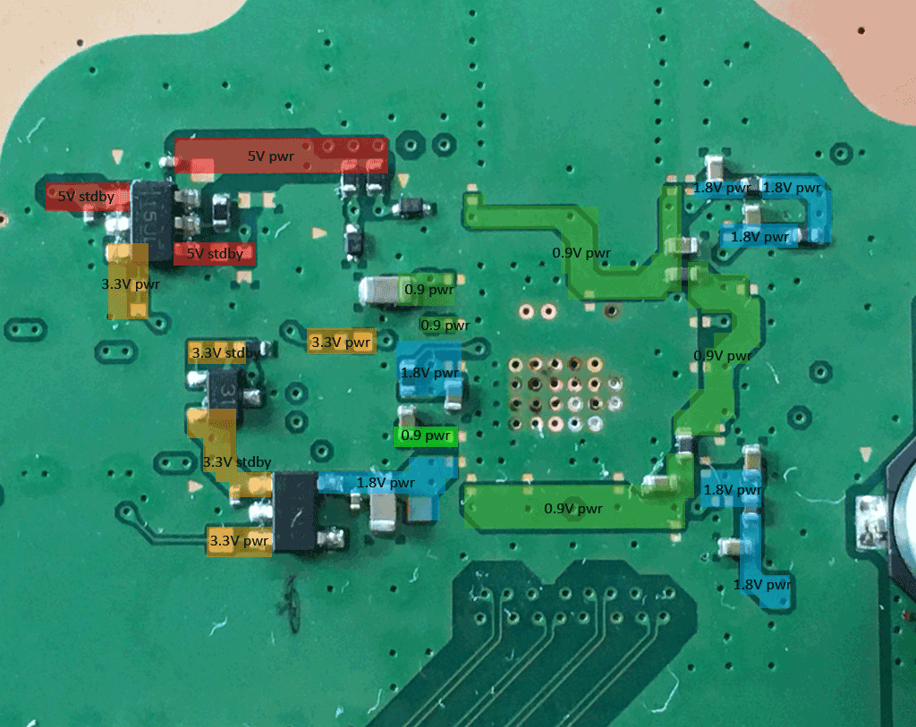
The 3.3V at this spot are coming from the southbridge. The 1.8V are generated on the backside at the 5 leg bug converter.
Hi Marvin
Thank you for the photos, so there is a difference between your photos and the one I found on a site. I think that there is no error in them. So the tensions I’m talking about are only present when the card is powered. So it’s normal that I can’t find them, so my card has no problems at this level. On the other hand, I have another which when I plug it into a desktop power supply (in the same conditions as the other), has the same voltage as in your photos while it is on standby! Does that mean I have a problem with my south bridge? I specify that I did not find a short circuit.
thank you for your help
on the other hand I don’t have the 5 v and 0.9 v power
You need 3.3V on the enable pins on these three dcdc bugs to get the 0.9V, 1.8V and 5V generated. If both 3.3V are missing, there is a problem with the SB itself or with the pmic for the SB.
Thank you for the response but I don’t think we understand it. How is it possible that the 3.3 v pwr and the 1.8 v pwr (in your photos) are active while the console is on standby?
Bare board boot sequence has 12v10mA constant standby power draw, that’s why they called standby voltage rails
yes I know there are rails present when the console is just powered on, the stb. And tensions that appear when you start the console: the pwr.
In my case as I said in my previous message I have pwr voltage which is present while the console is in stb. My question is how is this possible? Can we put a video here? if so I do it to make myself understood clearly.
Feel free to edit my images and mark the spots where something seems to be unusual and post them.
nope, standby power rails present before you hit power button.(Before console per on)They show up right after you plug in AC power cord
Hi
OK, I have the beginnings of an explanation. I had in my hands a functional edm10 100889021. I noticed that there are several models which explains the difference between the diagrams. On this model the tensions I am talking about are very present in stdby. Whereas on an edm10 100889011 model they are as on the Calvin diagrams only present in pwr.
So back to square one.
And happy new year to everyone


