I’d just compare against your parts board, it’s quite unlikely it’s going to have been suffering from this same fault, if you find anything that’s hugely out of whack lemme know and I’ll check on a known good, remember to check in both probe polarities relative to ground in either diode/resistance but just note this is not foolproof and would be better off checking continuity unfortunately I haven’t got around to mapping this connectors continuity on both sides of the board
Brown is definitely not ground… lemme double check where is goes…
Edit: Oh, its pretty close to it to be fair… never mind 
With black on ground I get:
Red: 42k
Yellow: 100k
Purple: 10k
Pretty different to mine then lol. I am going to check against my test boards to see what I get there with my multimeter but with them both having parts taken off I didn’t know if that would skew my readings.
Did you get anything on white on yours? Seemed off that it read nothing
Thanks
I can double check a bit later, but yeah I tihnk it was OL, all the ones I didnt mention were pretty close to the same.
When mine didnt work, it wasn’t the PU chip on the back, but the other 6 pin chip nearby. This connector also runs up to that and I had accidentally put it on backwards after knocking it off.
@Insomniac I haven’t changed that smaller 6 pin so should be on the right way unfortunately as it means further investigation. I have been checking resistance on neighbouring components and am struggling to find the specific issue causing the different readings.
On my parts board I have similar values apart from purple where my parts board has 11k. Apart from chip labelled BW do you know where else purple goes / comes from?
Purple runs to the larger of the 6 pins on the other side,the one nearest to the light sensor. Infact the pin in question is the corner nearest the light sensor also.
Yeah, did some tracing too and found that the 2 resistors going to the 2 lines that are backwards on mine purple and yellow were opposite way round to my test board which I have no idea why but replaced those to match test board and reading 10k purple and 100k yellow so just putting it back together to test and see if it made a difference
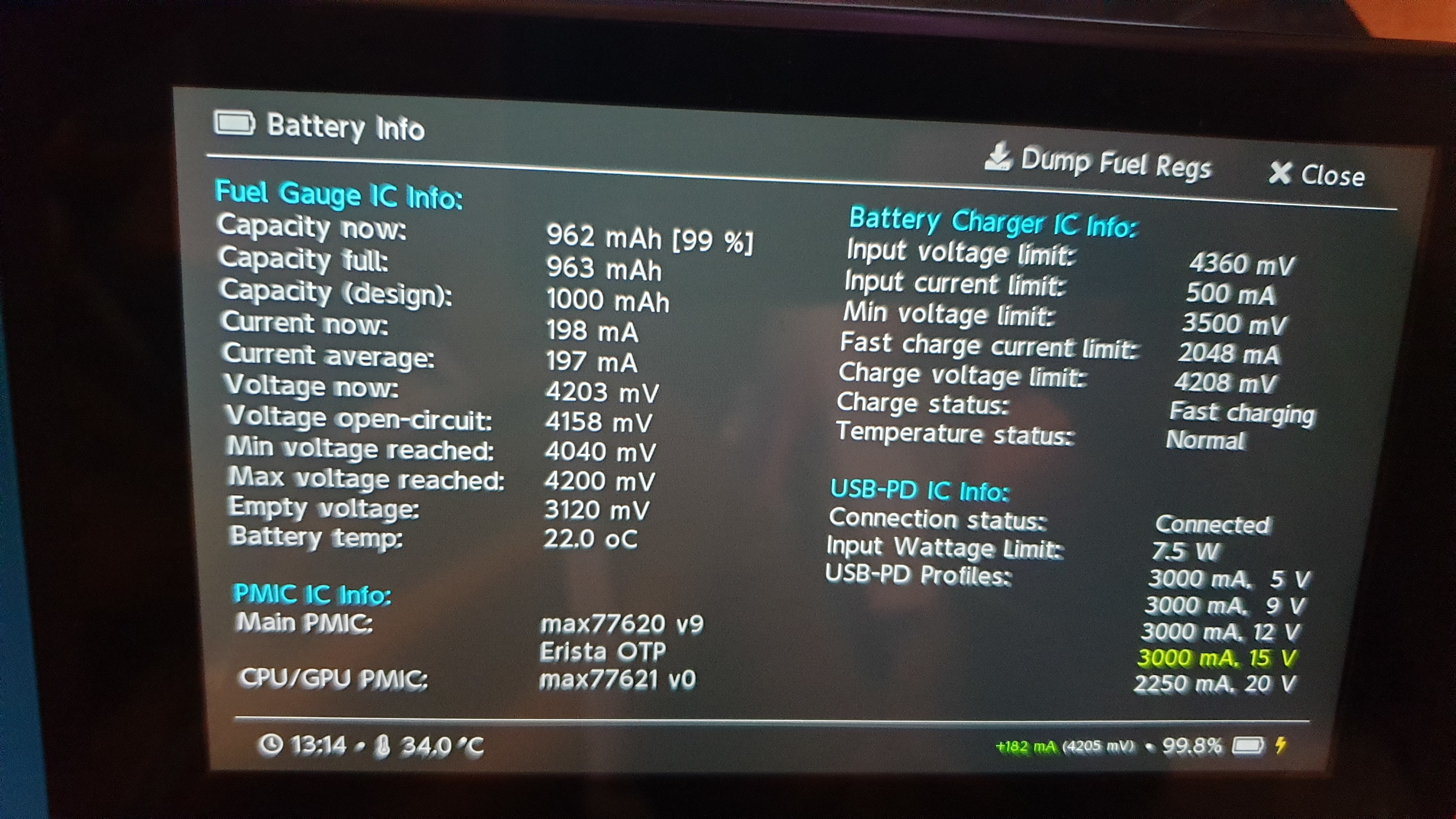
So now I can’t boot custom or stock from hekate. I can still get into hekate but it’s the same problem I had before where it wouldn’t boot when hekate reported battery as only 1000mah not the proper capacity but with 2 different batteries, leaving to charge for ages, several reboots and its made no difference, battery is still reporting 1000mah.
Could this be stopping it from loading firmware as it won’t let it draw enough current to boot?
Could the fuel gauge be faulty too?
It does charge the batteries at 15v and 5v, current charge is 4204mv so is full.
It’s not uncommon for Hekate to display the incorrect battery capacity until after what I believe is a certain cycle count (though I’m not entirely sure about this, presumably it’s pulling the info off the fuel gauge) so unless the fuel gauge has any obvious chips or cracks in the IC, bad joints, or corrosion below, then I don’t think that’s your issue.
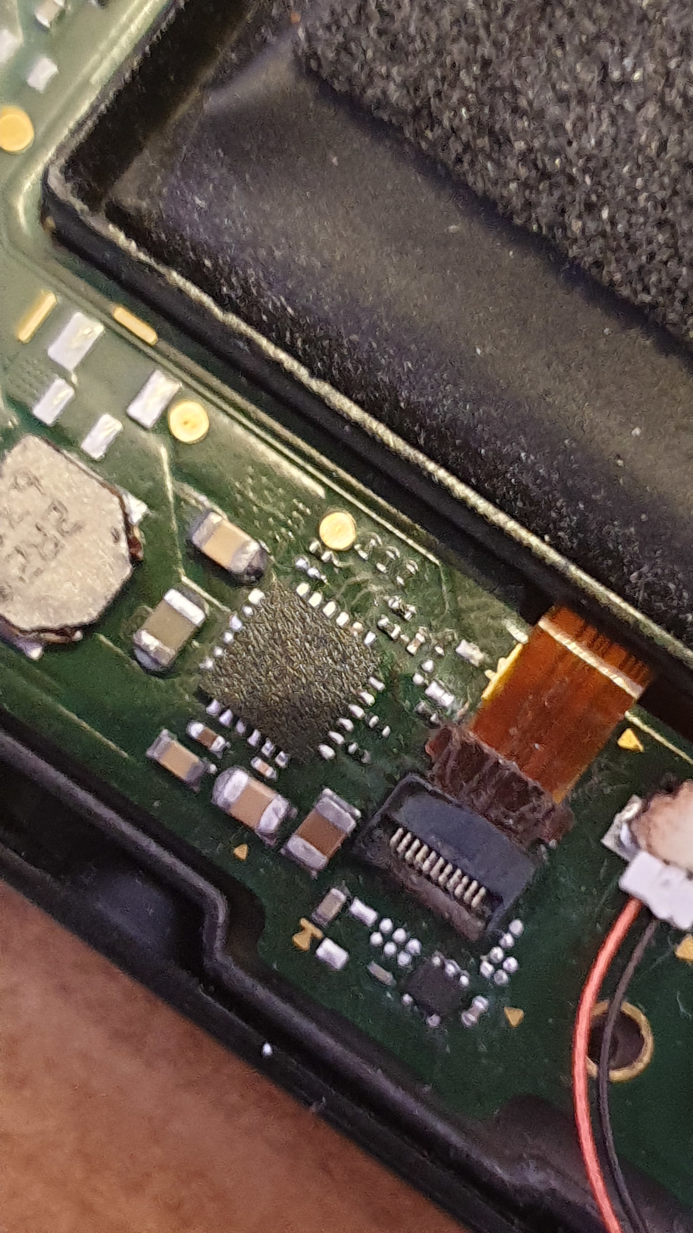
presumably it stopped booting stock via Hekate after your resistor swap at the JC connector? did you use hot air or just your iron? if you can take a photo of the BQ, battery connector and also the fuel gauge area, might be good to take a look as something in this area going wrong would be the first port of call.
Also taking a snap of the battery info section of Hekate would be good too, incase anythings changed since last time.
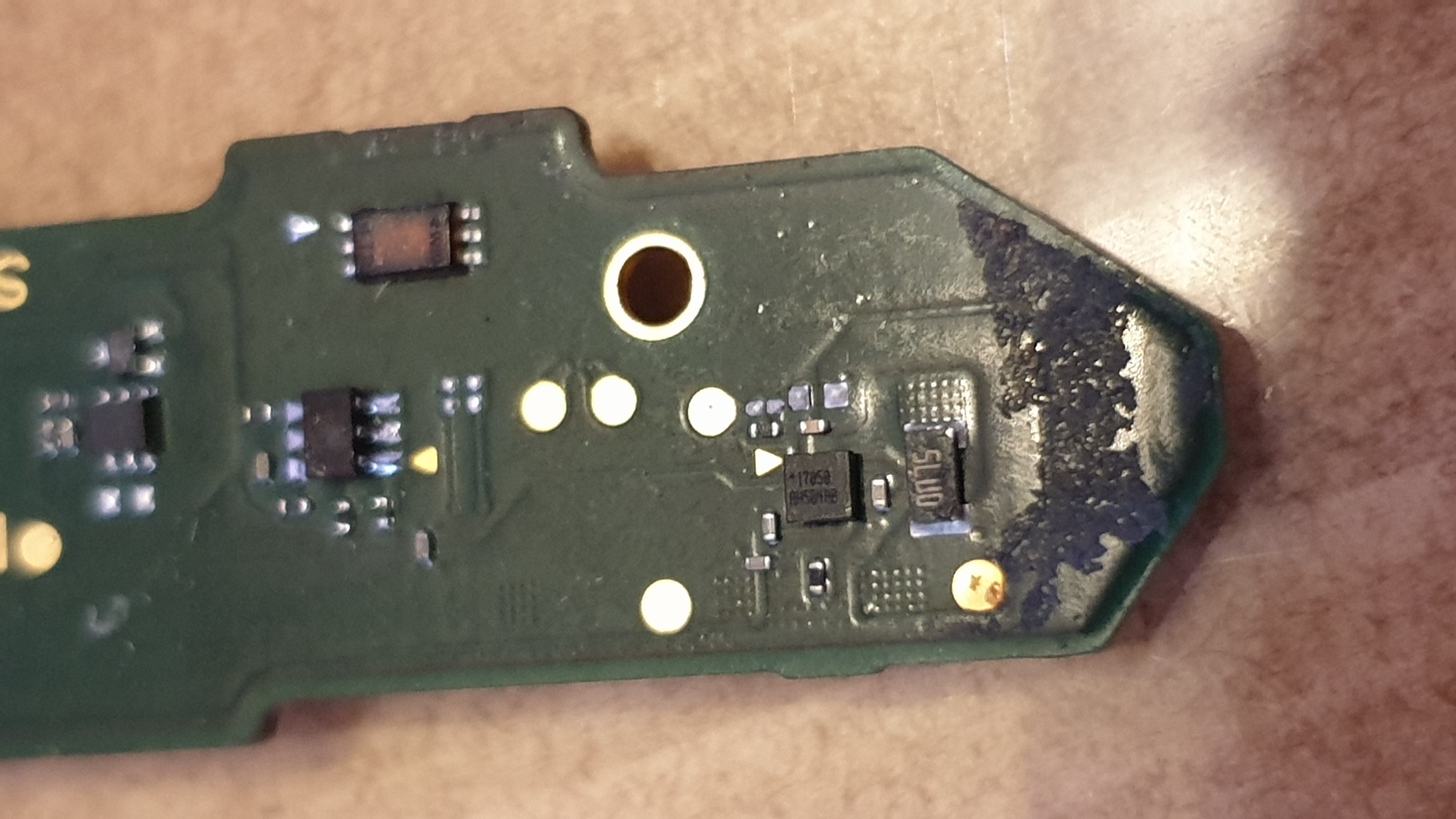
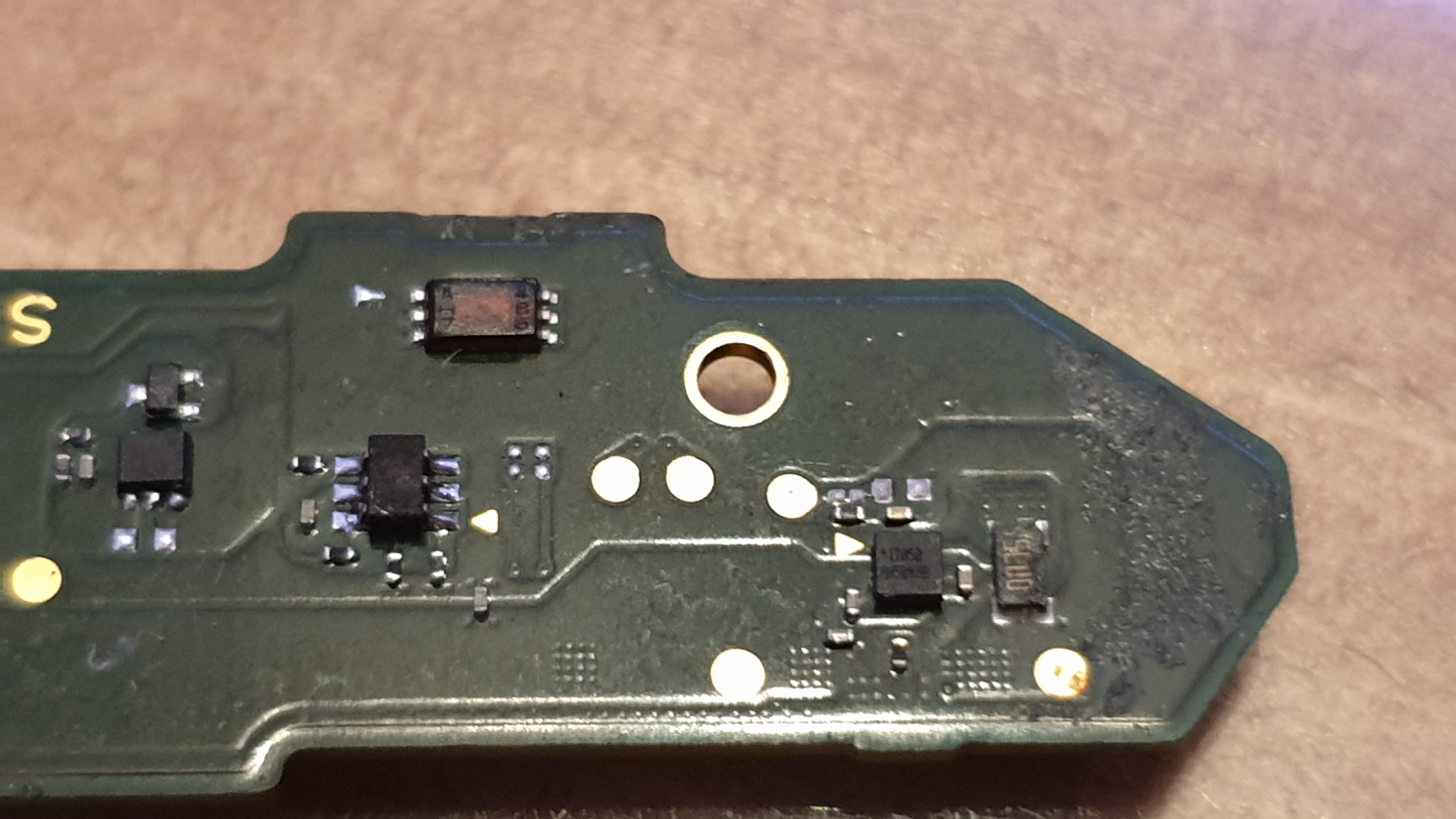
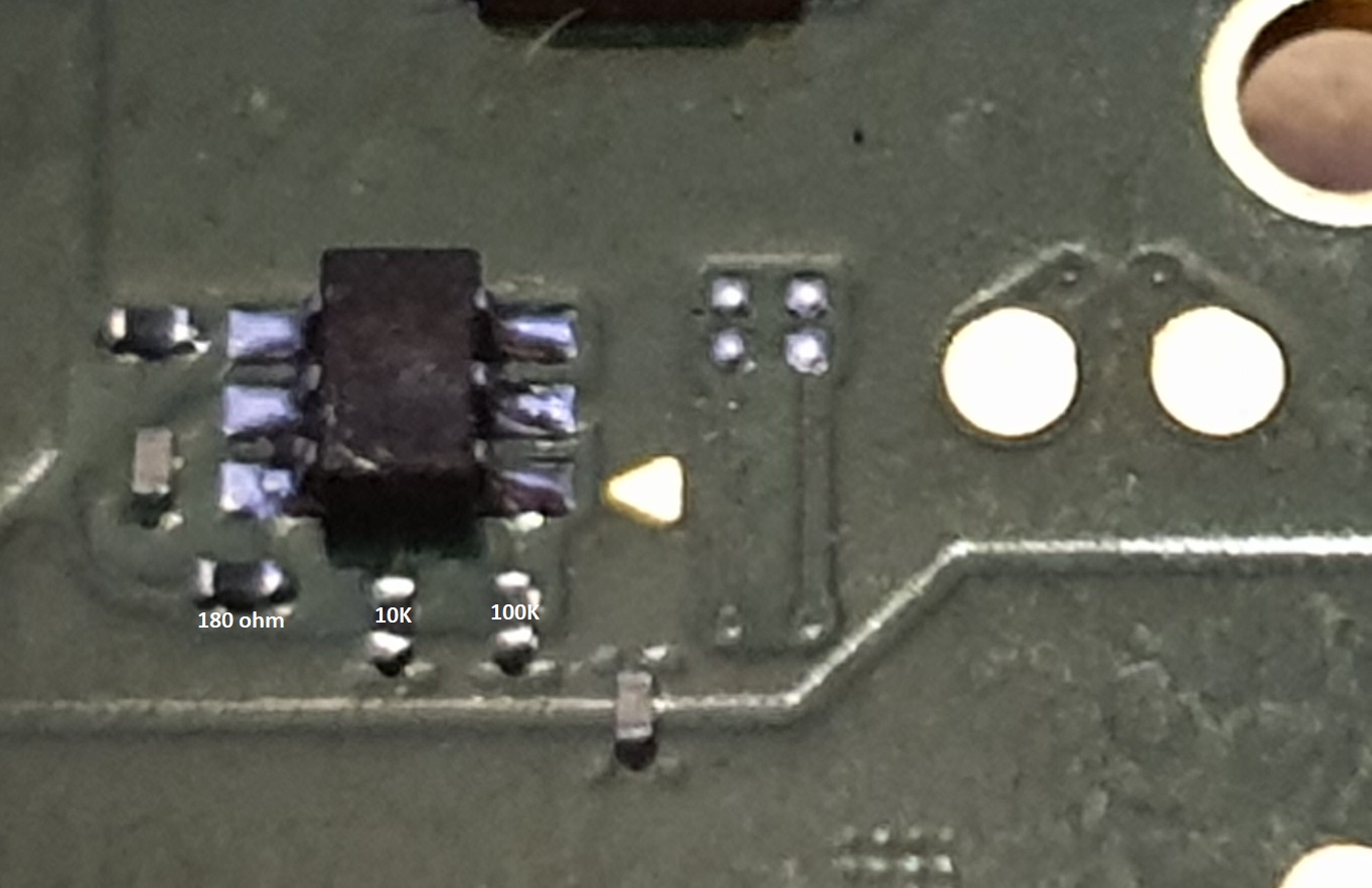
It was the below 2 resistors circled that I swapped as they were the opposite way round (value wise) to my test board and linked to the jc connector on the other side, now the readings on the connector are right.
Used hot air to swap them round
Also battery info as of now
Will have to take it apart again later when have more time to get photos for you thanks
One thing to note, I got fed up using the jig everytime to test so I put it to into auto rcm in hekate until I can get it to boot cfw from there again and it doesn’t work, even when enabled I still need the jig and volume + / power?


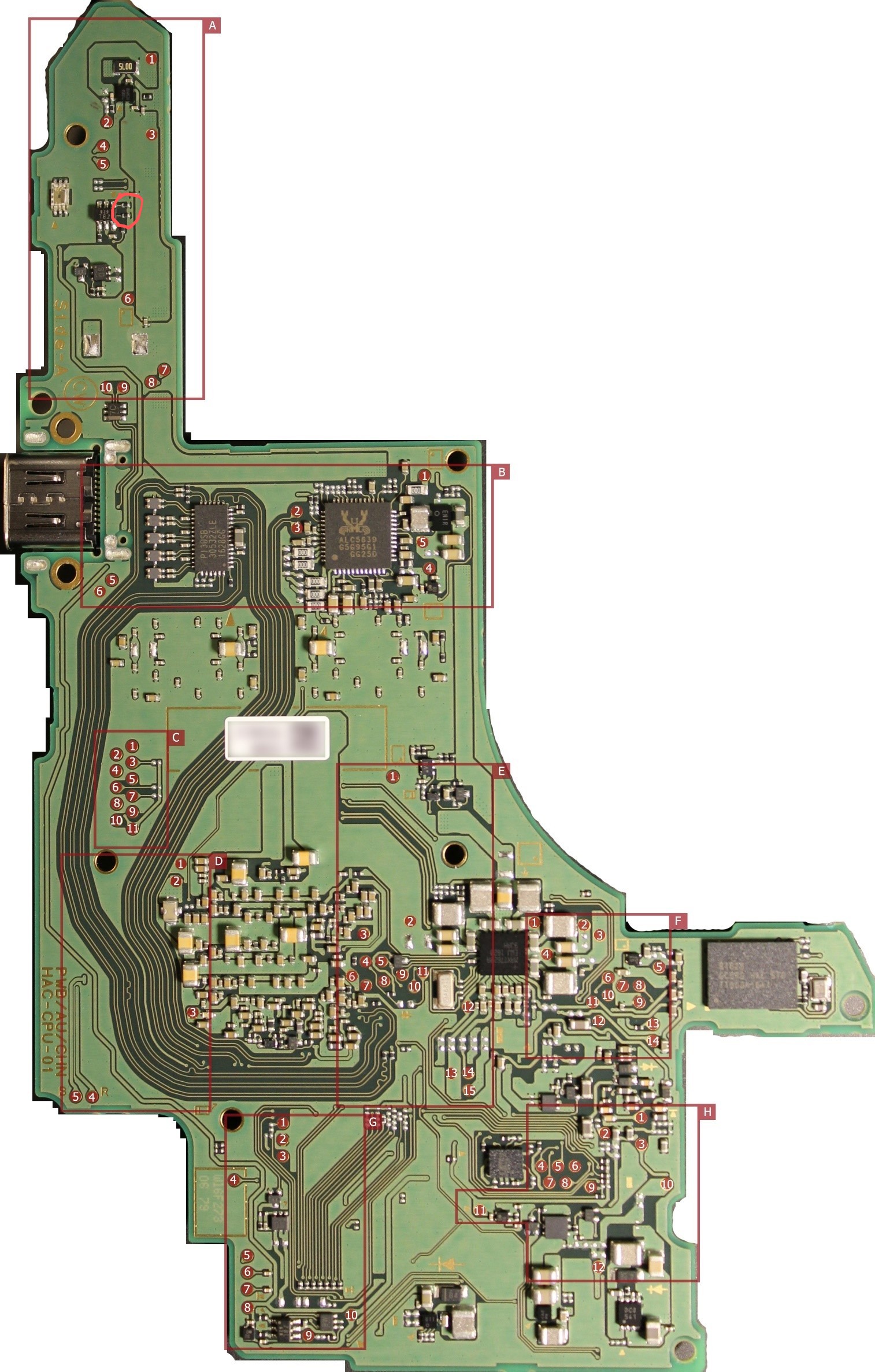
I don’t know if any of the following will resolve any of your issues, but if it was me working on this board I would be performing the following,
Replacing all components highlighted in red, and removing all in yellow (the LED for example I can’t imagine will work anyway)
If you see any more caps or resistors dotted around the board which look to have discoloured/damaged endcaps just go ahead an replace them as it’s not worth guessing if they’re good on power on.
Given that somebody at some point has messed with the passive values on this board it would also be worthwhile checking all resistor values surrounding IC hotspots, so I’d check that al the resistor values surrounding the M92, BQ, P13, and fuel gauge are correct and compare to your donor, I’ve had boards in before where 10K pullups and pulldowns have been incorrectly swapped out with zero ohm resistors…
The pads above the fuel gauge, the solder looks pretty tarnished and the large current sense resistor looks a bit eaten away which possibly implies liquid got in this area (dunno if that’s what that black gunk is in that area?) so may be worthwhile replacing the current sense resistor, and adding flux and reflowing the fuel gauge prior to just replacing it.
As for your joycon, I’d probably continue testing this wth another flex cable which isn’t quite so beat up as you don’t want to be second guessing yourself, you should be able to connect the joycon and use it within Hekate if the problems are resolved
Thanks for the pointers. Replaced everything circled in red and looked around all those ic’s. Near bq there was a capacitor where there should be a resistor and another resistor not reading correct resistance. Replaced those and one that was slightly out of range near the m92 ic. Left joycon now working in hekate but still no change on booting cfw or ofw from hekate and doesn’t boot from off.
Auto Rcm does work now too strangely enough.
Batteries still read max of 1000mah despite running flat and charging to full with 2 different batteries.
When discharging hekate shows 0% long before it shuts off. It was this same behavior when it wouldn’t boot before then when it read the battery fine it booted.
I haven’t reflowed or replaced the fuel gauge yet but think that’s next. Is it easy to swap from a donor or do you need to reball it first?
Great news ![]()
I don’t think this is a coincidence, probably the cap where the resistor should have been causing this one, and also likely preventing normal stock boot earlier.
Yeah I think thats next port of call as black screen and no boot logos could be the fuel gauge at fault
It’s easy but you have to reball with stencils and paste (or preformed solder balls if you prefer) just be careful with the IC as it is delicate. Alternatively you can buy the chip preballed from mouser etc
Thanks @Severence I’ve changed the fuel gauge and still the same scenario.
Is the big component on the edge of the board the sense resistor and does it matter which way round it goes?
Also, any chance you have a board you can check the values of the 2 resistors I changed round previously to try to fix the joycon problem as they didn’t look worked on but it’s only since swapping those that it’s stopped booting from hekate so would like to verify. My board is the hac cpu 01 version of that helps
Thanks
Yeah the one with 5L00 printed on it, doesn’t matter which way round ![]()
I’d check to see if the battery info section is now reporting correct info now (possibly after some time charging/discharging) to see if that is now resolved, I’d also take the oppurtunity to re-test that you can read and write EMMC partitions (as that would be the other cause of black screen no boot)
Has the burnt fuse count changed at all out of interest or are you still on the same OS version as reported?
That area where you found the cap where there should have been a resistor, if it was leading to the BQ IC (for example) then might be worth swapping out the IC incase it’s caused some damage failing all of the above
Might also be worth checking the battery connectors solder joints too as that could cause the same symptoms as a bad fuel gauge